This is no personal attack or something, its needy offtopic realism for all, so that maybe someone could wake up to reality.
5 hz/100 khz?
They want to trigger the placebo effect in potential buyers.
If you wanna buy please listen to this beforehand:
YouTube - Sound test 20-20000 hz [HD]
Take a look at their distortion lines. There they are comparing themselves to "competitor". Question is, what amplifier have exact that white line or is it just made up? They have probably payed someone to paint it for marketing.
How is their 20khz so much lower distortion than other frequencies?
They are leaders of marketing and nothing else, except proof is on table which i cant see happening. Companies like this one and many others, knows how to get attention, and they use it, but only few people see it.
Hi,
I very much agree with you and your post is real evidence that people are not all stupid (thankfully).
I know ... maybe too much and this is a price to pay since I was already at university. Prof. classic was stupid and instead of actually teach the subject, preferring to teach how to show beautiful things (said it was not really important but what it seems) So do not be surprised if companies painted beautiful curves,
have no other real way to convince you.
Regards
PWM is old stuff, except:
"PWM is a comparatively recent technique, made practical by modern electronic power switches, although one of its earlier applications was in the Sinclair X10, a 10 W audio amplifier available in kit form in the 1960s."
Pulse-width modulation - Wikipedia, the free encyclopedia
So no need to re-invent it. Most class d amplifiers are made with same tech, but used in different ways for each engineers design.
And hiding important details before release is a smart thing to do, because leaked info is what make companies copy each other. If two engineers who design their own amplifier comes to the same solution, i cant see anything wrong in that they both use the same solution. Even if one would come to same solution after already knowing it from another ones design.
More info about the Sinclair X10 (scroll down):
http://spectrum-zx.chat.ru/amps60s.htm
 OT personal remarks removed. Any more will result in long sin-bin time for the offenders. Warnings issued, points given.
To TicksNLeeches.
----------------------------------------
If you really want to know how I tackled and overcome some problems such as protection or intermodulation distortion, or how it works "(dc current feedback)" APC ", you'd just asked me.
But you do not want to know how I did, obviously reading what you have always written against me (I'm not the only one to have understood).
since my first post on "SMPS400 HYPEX " you've only heard attack.
It is easy for you that you're anonymous. very good. I'm not anonymous in this forum.
Sooner or later it will come out because it attacks me.
Why not attack other companies that you know which are incapable of solving the problems of their amps?
Regards
Hi AP2
The performance of your amplifier is below average, according to the measurements it performs similar to my first self oscillating attempt a few years ago, a 2x150W UcD clone with LM311 and IR2010 and built-in 12V SMPS. (around 0.01% THD floor, 0.05% THD at -3dB, 0.1% THD at -1dB from clipping).
Now, after many changes and improvements (and making it different from UcD too), I'm getting better THD figures and lower output impedance at much higher power, switching at just 240Khz with standard double sided PCB, and high propagation delay (300ns, probably next thing to improve). I get THD around 0.005% at 1khz and 700W/4R (-6dB), rising to around 0.05% at 4Khz and -1dB from clipping (>2000W/4r). In my modulator THD starts to rise above 2-3Khz due to loss of loop gain, though.
At low frequencies (or low powers <500W) THD from the preamplifier and various signal conditioning "gadgets" dominates, around 0.005% or below, up to -3dB (freq<1Khz) and not dependent on load. Note that currently my output stage operates in D.C.M. (free from dead-time artifacts) until 500W/8R or so.
In other words, you still lack a lot of "efficiency" as a class D designer. You used a lot of advanced electronics resources (like 4 layer PCB or 600Khz switching) to provide under-average performance. This is part of the learning process, though, it took me a few years to find these solutions and it's going to be similar for you.
Traveling on your own to strange places and doing things you have not done before may help a lot to free your brain from stress, then new ideas come easily... At least it works for me.
Last edited:
Now, after many changes and improvements (and making it different from UcD too), I'm getting better THD figures and lower output impedance [cut] In my modulator THD starts to rise above 2-3Khz due to loss of loop gain, though.
You mean you have implemented this schematic in attachment, provided by Bruno?
")
Attachments
Hi AP2
The performance of your amplifier is below average, according to the measurements it performs similar to my first self oscillating attempt a few years ago, a 2x150W UcD clone with LM311 and IR2010 and built-in 12V SMPS. (around 0.01% THD floor, 0.05% THD at -3dB, 0.1% THD at -1dB from clipping).
Now, after many changes and improvements (and making it different from UcD too), I'm getting better THD figures and lower output impedance at much higher power, switching at just 240Khz with standard double sided PCB, and high propagation delay (300ns, probably next thing to improve). I get THD around 0.005% at 1khz and 700W/4R (-6dB), rising to around 0.05% at 4Khz and -1dB from clipping (>2000W/4r). In my modulator THD starts to rise above 2-3Khz due to loss of loop gain, though.
At low frequencies (or low powers <500W) THD from the preamplifier and various signal conditioning "gadgets" dominates, around 0.005% or below, up to -3dB (freq<1Khz) and not dependent on load. Note that currently my output stage operates in D.C.M. (free from dead-time artifacts) until 500W/8R or so.
In other words, you still lack a lot of "efficiency" as a class D designer. You used a lot of advanced electronics resources (like 4 layer PCB or 600Khz switching) to provide under-average performance. This is part of the learning process, though, it took me a few years to find these solutions and it's going to be similar for you.
Traveling on your own to strange places and doing things you have not done before may help a lot to free your brain from stress, then new ideas come easily... At least it works for me.
hi eva,
You measure are very good,..many good.
Goal of DXA-400 is not efficiency (electric efficiency)
Target is a amplifier with audiophile performances with voice and high frequency of audio band without classic IMD.
4 layers for low sn/R (have 106 dB at 600KHz of carrier)
driver have 30nS DT and 80 nS from modulator to gate mosfet.
is not easy to explain the problems I had to overcome at these speeds.
I think you have a good experience, everything becomes more difficult, the protection must be very fast.
DXA-400 has 0.05% THD + N at 430W (4R) (I think the lowest for an amp this range) and flat up to 50KHz.
Sound is not recognizzable as D Class amplifier.
Last edited:
I remembered the most important thing.
This is a commercial product, therefore, no style B &O and even UDC.
I have a passion for the modulator "MXD" because modulation is a result (not direct modulation), FB2 is not really falling on a feedback signal. (I erroneously called "FB2)
You're absolutely right, it's wonderful to travel..., I really need
Regards
Last edited:
You mean you have implemented this schematic in attachment, provided by Bruno?
This schematic was the second thing that I tried to implement after the basic circuit with one passive pole, but any direct implementation just won't work. It does not provide adequate frequency response resulting in HF peaking, it does not provide reasonable phase margin resulting in instability when coming out of clipping (and terrible sticking to the rails due to integrator "memory"), and worst of all, it won't start oscillating easily on input signal zero crossing like the basic circuit (it may never start on itself).
I had to rearrange the existing components, and add more poles and zeros and gadgets, thus making it conceptually different from the figure shown on Bruno's paper, to make frequency response ruler flat and get over 45 degree phase margin at the highest crossover frequency possible, and prevent the integrator from integrating what it shouldn't, thus making it useable.
Bruno didn't like active poles for a reason or two
I may have enough work to get one or more patents, but I don't believe in patent systems. If you join the patent game, law will always help anyone richer than you to take over your ideas (and your money). It's a system intended to make rich people richer and poor people poorer from the beginning, and I'm in the latter group so I can in no way benefit from it.
Last edited:
If you join the patent game, law will always help anyone richer than you to take over your ideas (and your money).
Not only that, but patents stop tech advancements which could be done by many people around that think different than the inventor, and make it even better. Class I is an example of that, and its only available for deep pockets or diy. Not that i miss it so hard btw
Hi
I am interested in building a couple of mono block amps from you DXA-400 (or maybe DXA-600) kits with a separate switching PS for each. Your website currently says that both of these amp models is sold out. Could you tell me when (or if) these amps will be available again? could you also tell me what the advantage of running the PTU-2 board with the DPS-400 supply is?
Also, I have been unable to find and reviews or information from others who have built amps from your modules, could you direct me to some more information from people who have actually implemented your amps.
Thanks very much for you help.
Regards,
Dave.
Hi
I am interested in building a couple of mono block amps from you DXA-400 (or maybe DXA-600) kits with a separate switching PS for each. Your website currently says that both of these amp models is sold out. Could you tell me when (or if) these amps will be available again? could you also tell me what the advantage of running the PTU-2 board with the DPS-400 supply is?
Also, I have been unable to find and reviews or information from others who have built amps from your modules, could you direct me to some more information from people who have actually implemented your amps.
Thanks very much for you help.
Regards,
Dave.
Hi,
Thanks for your interest.
DXA-xx series will be available by the end of August.
I recommend using the new DPS-500 with DXA. (230/110VAC)
very compact and clean with very fast response has been developed for optimum performance of DXA amplifiers. (DXA-400 delivers quiet 470w rms 4R)
I'm sorry but I have no info on individuals who have this new amplifier.
The first produzuione has been given to companies in high-end market.
You can ask support "AudioPower for the best combination in reference to your loudspeaker.
Best regards
Hi,
On this much discussed new amp, although the first prototypes appeared for the first time on the web, in 2007 under the name "MXD" by Micro Devices. "Today" MDI ", R & D for products AudioPower.
I intend to announce a new release will be available at the end of July. now this is a date certain. maybe it's good news for some who have followed us with hundreds of emails.
Some info on the MXD, just to clarify.
When this project started, it was not easy to move between UCD & B & O patent's . but just this difficulty has led us to seek a new way .in fact is currently the only amp that not plays on the NFB's a stretch to get a completely flat response up to 60kHz.
MXD consists of a primary FB (pre-filter) the right to initiate and maintain oscillation.
was then contrived a passive module (balanced modulator). This typical circuit used in RF, has two inputs and 2 outputs.(or depends on how it is used)
one of the outputs is the resultant modulation (this includes the frequency of carriers in the opposite phase). This signal is compared with the input signal and the frequency carrier, operating on the modulator. (This consists of two fast comparators).
sorry for simple explanation. just to give you an idea about the technology used on this amp.
it is obvious that the performances were obtained also possible the use of new drivers (up to 25ns DT) and protections "Intelligent".
we also The APC circuit "Active power control," contributes to a new sense of listening, in fact it is able to vary the overall gain, in relation to the load, in real time without distortion.
it is known that a reactive load, the currents vary depending on the frequency. (remember that amp, modulate current simultaneously at very different frequencies).
(it is obvious that we wanted to get a very clean amp, looking to use with excellent speakers who have the crossover.
in a multi-way, amplifier is connected directly to a speaker and works only in a narrow range of frequencies. This does not require special performances in extreme linearity vs. load).
During the tests, with an 8-channel recorder with a track on video(analyzer), listening to the songs, have been highlighted significant absorption peaks.(and modify sound)
eg. of trumpet and electric piano, voice, or female (jazz) and bass+trumpet.
I personally am convinced that the values already below optimal (I'm referring to the amp distortion and linearity), all amplifiers have a great sound ... unfortunately it does not. independent of the good measures, required further work on an amplifier, these independent if amp is class D or AB.
audiopower has applied this concept to the oldest and simplest amplifier SDA-300. develop around IR2110 driver.
It may seem that I want to encourage the sale of amps. no, my intention is to repeat the same things, like .. the driver is important. The comparator is a critical and perhaps I have the satisfaction to see that some companies .. evolve.
N.B.
anyone who wants to attack me?... maybe today, not have reason.
Regards
Roberto P.
Hi,
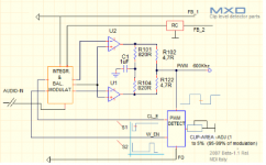
As promised in this thread, I will try to where possible, to introduce some new techniques developed for the MXD amplifier.
Today, the concept used in the show circuit "clips detectors" and part of the circuit that receives signals from the detector.
I think the pic is very clear and simple.
explanation:
detector circuit, Generates two basic signals: S1 (CL_EN), this is normally continuous high state (if level is not in the clip area). goes down for a period equal to the percentage of clips.
the other signal is W_EN. This is repeated always the same and contains two components.
CL_EN windowed and one pulse.
This circuit is not influenced by other factors eg. thermal drift, or when the amp works exhausted.
in the diagram: "Integration & Balanced modulator," I decided not to use old schol as simple pair of diodes in the op-amp fb.
This simple how old system has many flaws, not absolutely perfect for clamp signal, whereas the audio is not a continuous signal at a fixed frequency. Also, the knee of the curve of diode is highly variable with temperature, etc..
So I developed a system that is perfectly in line with the performance of this amp.
considered that an audio input signal (eg amplifier in class D) is under the cycles of the carrier frequency (or oscillation).
Considered that an audio input signal (eg. in amplifier in class D) is under the cycles of the carrier frequency (or oscillation), it makes no sense will continue to work a circuit interposed in the signal path, so I opted for a circuit type "samples & old. "at this point is simple, easy integration with CL_EN signal produces a voltage level proportional to the cycles that is kept in a small capacity (W_EN signal, is used to refresh). reset signal, disconnects this circuit.
benefits:
Absolutely repeatable, not unaffected by external factors.
Adds no distortion in the maintenance phase.
Perfect fast response, related to the transient (loses 30ns)
All performances of this new amplifier are the same as cold as when it is exhausted.
it is obvious that the development of MXD does not stop at two amplifier models. will soon be available for OM (I think within the year) a hybrid with a dissipating surface (vertical mounting with two screws 4MA-18 pin in line). 150 and 300w for high frequency driver. It needs only a simple torus filter and PCB and provides 104dB in range (10-60kHz) without PCB (assembled in a simple fiberglass pre-drilled). This circuit incorporates all the functions developed for the amplifier MXD.
The next, with other concepts used in MXD modulator.
Roberto P.
Attachments
Last edited:
- Status
- This old topic is closed. If you want to reopen this topic, contact a moderator using the "Report Post" button.
- Home
- Amplifiers
- Class D
- New DXA-400 class D Amplifier-Info