Voxac30:
12000uF shuld be well-enough (to kill bus pumping). Mosfets mainly depend on your supplies, and purse. If you can get switching mosfets designed for class-D (for you I reccomend IRFB4228 or FDP2532), its the best. If cannot for low p
The original schematic has some I'd say errors. (it works, but not too good performance)
You should read the reccomendations for coils by Pafi, look at my calculations too. If you do the calculations youn won't have problem with inductor.
You can use the classic relay protection, it's the most reliable, when you can get the right relays.
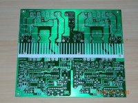
You can use one-sided PCB, but if you need very great performance (kW and low noise), double sided PCBs with proper ground planes is essential.
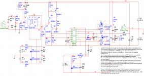
I attach my schematic (I USE IRFB4227 insted of IRFP240!), where switching freq is around 220kHz, and there's no input noise.
An externally hosted image should be here but it was not working when we last tested it.
Dzony: i killed noise to a minimal level. I had clues about noise, from your post i got sure. I increased 100p to 1n, and decreased 47k to 22k at input. If all the inputs are open, then there is almost audable hiss (with a horn loaded cab..., with 0,1W output you cannot hear noise)
http://www.diyaudio.com/forums/clas...200-watts-using-2-mosfets-75.html#post2406217
hi all back to basics that is ucd mode . i hope there will be no issues with multi channel. my current project based on lorylaci ucd tested and improved in terms of noise and harmonics.
Attachments
D
Deleted member 148505
the amp sound is excellent , except the issue of powering the amp without a speaker load everything is o.k.
bias supply you mean the 12vlts to feed the ir2110?
yes mosfet's driver supply
yes mosfet's driver supply
i tried it but same results . i used irf640 instead of tip41 for each channel
Class d can be fussy about a speaker load.
The irs2092 outputs 17 volts DC if no speaker is connected.
Connect a speaker and it drops to zero.
have you ever tried making a four channel amp of the irs2092, with a single power supply?
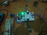
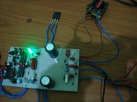
did you face similar issues when the amp is on, and a speaker is removed from either one of the channels?testing irs3000d first try working perfect.
dc supply 55v,
irfp250 fets,
ring not hot,
ic's are not hot,
after signal input the active led is on,
pls some one guide me to adjust the preset 10k,
dc supply 55v,
irfp250 fets,
ring not hot,
ic's are not hot,
after signal input the active led is on,
pls some one guide me to adjust the preset 10k,
Attachments
http://www.diyaudio.com/forums/clas...200-watts-using-2-mosfets-75.html#post2406217
hi all back to basics that is ucd mode . i hope there will be no issues with multi channel. my current project based on lorylaci ucd tested and improved in terms of noise and harmonics.
hello stewin see some changes in your amp gt how to use the output pin 7 instead of pin one on the 311 lm well I'll see how it works, but usually has a lot of noise this amp in its original design,
but if you add a 1 nf capacitor at the input you reduce drastically the treble
why not hear background noise, just use it as subwoofer????
best regards to the forum
Hi Steve,
...also feeling sad if you would need to scrap your amp, especially because you are satisfied by the sound. So my brain was digging for further potential reasons of the starting issue.
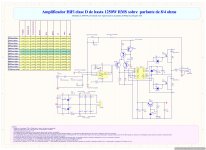
From guaranteed output swing of the TL074 your level shifter can happen to remain slightly conductive even when the TL074 output is HIGH.
From calculation this can lead to an input signal of more than 2.5V at the input of the 4049.
You can easily try if this is the reason by changing the 6k8 resistor at the input of the 4049 (R31? hard to read) down to 5k6 or 4k7.
Good luck
Markus
...also feeling sad if you would need to scrap your amp, especially because you are satisfied by the sound. So my brain was digging for further potential reasons of the starting issue.
From guaranteed output swing of the TL074 your level shifter can happen to remain slightly conductive even when the TL074 output is HIGH.
From calculation this can lead to an input signal of more than 2.5V at the input of the 4049.
You can easily try if this is the reason by changing the 6k8 resistor at the input of the 4049 (R31? hard to read) down to 5k6 or 4k7.
Good luck
Markus
thanks for the reply . i am facing serious issues with irs900 both thienchay and detex they work for a short time or a few days and fail i have had three different experiences .in all the above the voltage was
>>> +/- 70vlts about 6amps and filtering caps were 6800uf per rail.
>>>the load was 3ohms to 8 ohms
>>>all the output fets were one pair irfp250n
>>>all the inductor i used was etd 33 or ee 33 , 15turns and 1mm gap on both legs using a piece of CD or DVD disc
>>>switching frequency was 250khz normal on the thienchay and detex layout
two projects had two channels one project had four channels.
i am thinking maybe busspumping, slow fets ("but dismissing it because big proffesional companies powersoft use irfp250n") , non ucd topology or core saturation . please help i am really confused .
i have another irs900 three channels which has survived for one year plus without any issues except bowing fuse when one output of either channel ,a speaker or load is disconnected when the amp is on. all the specs are like the above except the voltage is +/-39vlts.
i will post photos later.
Basically it can, but with 200V MosFets running from +/-70V rails it is not likely.hi all can bus pumping cause class d to fail?
thanks for the reply . i am facing serious issues with irs900 both thienchay and detex they work for a short time or a few days and fail i have had three different experiences .in all the above the voltage was
>>> +/- 70vlts about 6amps and filtering caps were 6800uf per rail.
>>>the load was 3ohms to 8 ohms
>>>all the output fets were one pair irfp250n
......
i have another irs900 three channels which has survived for one year plus without any issues except bowing fuse when one output of either channel ,a speaker or load is disconnected when the amp is on. all the specs are like the above except the voltage is +/-39vlts.
i will post photos later.
Most short comings in layout, gate drive, snubbering and Qrr of the MosFets body diodes translate into pain for the MosFets. Detecting the most dominant short coming(s) is only possible with detailed measurements of the critical load situations using a fast oscilloscope.
Of course without any measurement you can be sure that the MosFet stress grows overproportional with the rail voltage.
So your observation that +/-39V is fine while +/-70V shows issues with reliability is nothing strange.
...sorry that I cannot offer a simple cure.
With 15 turns on an ETD34 and approx 1.1mm gap (CD) in all legs, I would expect an inductance somewhere in the range 10uH...15uH and saturation somewhere between 30A...45A.
Nothing to worry regarding saturation during realistic operating conditions.
For my personal couriosity:
Do you use solid wires, or stranded wires- which thickness?
How much self heating does the choke show during idle, when running from +/-70V at 250kHz?
Nothing to worry regarding saturation during realistic operating conditions.
For my personal couriosity:
Do you use solid wires, or stranded wires- which thickness?
How much self heating does the choke show during idle, when running from +/-70V at 250kHz?
i use solid wires about 1.2mm - 1.8mm . and there is no core heating at all very cool.
>>>i think i should increase inductance about 30uh . i faced similar problems with ejtagle nonucd 200watts(" i was using t106-26 with 1mm cut by a hacksaw and 20turns") it used to fail at high spl if i used a 4 ohm subwoofer
>>>but after increasing the turns to 33turns every thing was o.k . i have used up to +/-47vlts with just one irf540n and one irf9540 and 4ohms load at high spl for a prolonged time and it did not have any issues at all. >>>also i have used 5channels with one powersupply +/-47vlts and in one body without any issues at all BTW the sub channel was bridged and had a load of 8ohms .
but because i need more power that is why i went the irs900 and aud600 way.
Last edited:
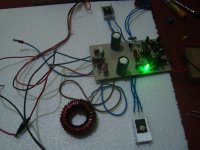
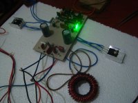
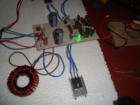
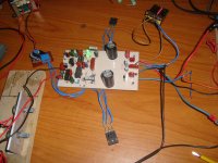
managed to make them stable enough that i've decided to case them up and use them as the resident sub amp.
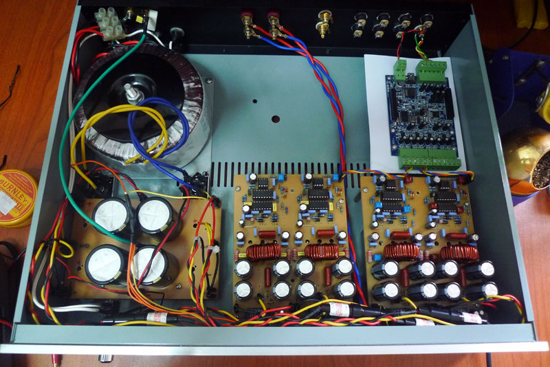
the output inductor goes too hot after 2 hours of movie run with huge bass so i've added an 80mm fan blowing to the pcb. gonna find another fan and do a permanent installation. the output mosfets are mounted to a heatsink underneath the pcb. the blue pcb on the top right is a 2x4 balanced minidsp to provide all the necessary dsp processing to the amp.
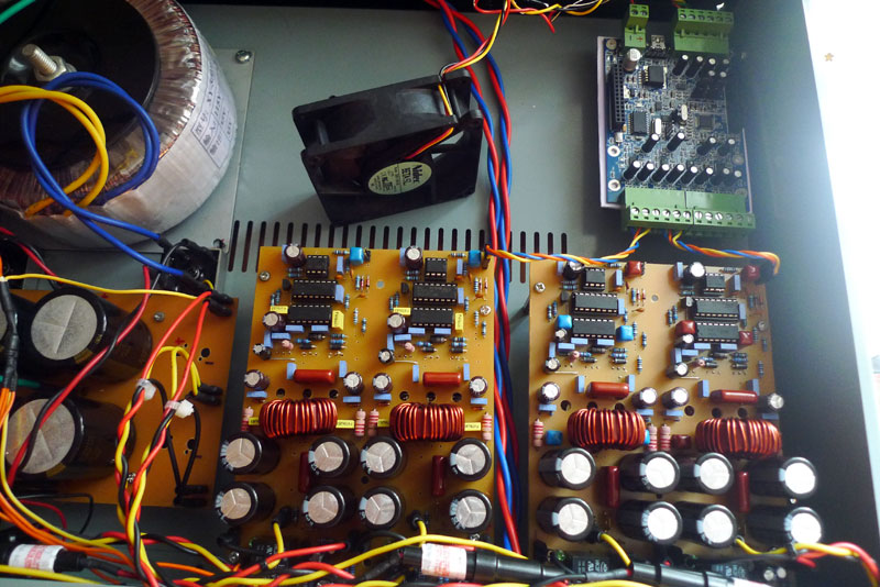
they're quad channel irs900d bridged into 2 channel powering a 4 ohm sub. switching frequency are reduced to 250khz, output inductor are made from T106-2 iron toroid with 21uh inductance. output mosfet are irfb5615.
each of the bridged channel powers one of these 15" diy sub:
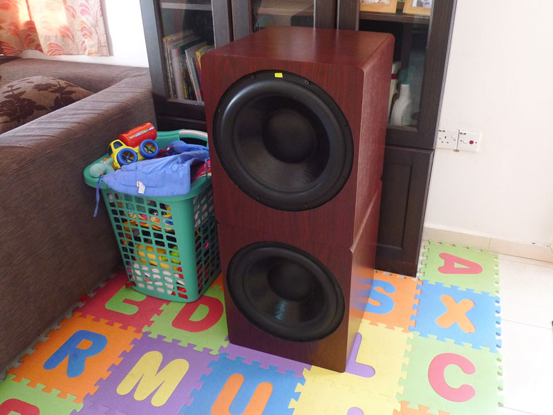
in room frequency response of the subs powered by the amp:
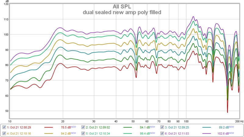
stopped at 102db before i could see any compression limit on the sub. don't wanna break the house.
hi paskal have you faced issues with the four channels you made or is it doing well?
- Home
- Amplifiers
- Class D
- UCD 25 watts to 1200 watts using 2 mosfets