I took the temperature after about a hour running at moderate volume into a 2 ohm load: UcD type Class D Amplifier - YouTube
Tekko,
Nice job man! �� It sounds great - very easy and lots of volume there for such an unassuming little circuit. It wasn't clear if the temps displayed by the IR thermometer was in degrees C or F?
Which circuit schematic did you end up using for your build? Can you point me to link?
Regards,
X
Nice job man! �� It sounds great - very easy and lots of volume there for such an unassuming little circuit. It wasn't clear if the temps displayed by the IR thermometer was in degrees C or F?
Which circuit schematic did you end up using for your build? Can you point me to link?
Regards,
X
The temp was in deg C.
This is the basic circuit used: http://i.imgur.com/poN8eVz.png
But i replaced the shunt regulators with some LM7x series 5V regs.
This is the basic circuit used: http://i.imgur.com/poN8eVz.png
But i replaced the shunt regulators with some LM7x series 5V regs.
Tekko,
Thanks for the circuit. What is the main difference between this one and he circuit posted at the beginning (post 13 I think)? Sorry for the newbie questions. Can you also point me to a description of how the circuit works in words? I am having a hard time seeing how a single op amp is able to serve as the input buffer amp, comparator, and sawtooth pulse generator to make then PWM modulator. Amazingly simple design but it is described in words somewhere that would be very helpful.
Thanks in advance.
Regards,
X
The difference is the way the comparator output is configured, instead of beeing open emitter in the original, i made it open collector.
The circuit is self-oscillating, using post filter feedback. It is not clocked.
You can find some info by googling "Universal Class D"
The circuit is self-oscillating, using post filter feedback. It is not clocked.
You can find some info by googling "Universal Class D"
Last edited:
D
Deleted member 148505
Anyone has a guess on how hot a 3A(source/sink) gate driver such as IR2010 or FAN7392 will get with 20 ohm gate resistor and mosfets with a total gate charge of 100nC at 400kHz ?
At 400ish kHz even with 30nC gate charge(IRF540) a IR2010 gets pretty hot.
Something tells me this will not even work at all.
These gate currents are scary!!
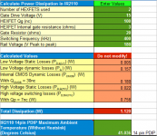
I've created a spreadsheet for calculating the approximate dissipation of the gate driver IC (based on AN-978) (Must be opened on libre office/open office) Feel free to edit if you found errors in calculation.
2pcs mosfets with total Qg of 200nc running at 400kHz is not safe without active cooling. Calculated dissipation is 1.1W (close to 1.4W max of 14pin PDIP IC case) and in reality, the actual dissipation might be worse than the calculation.
The result of the approximate dissipation shows that the surrounding air at the IC must not exceed 41 deg celsius for safe and reliable operation. I think it can be done with a heatsink on the top of the IC and active cooling to move the air around it. (Active cooling is needed because the ambient temp (inside the amplifier case) will rise when the IC or the amp itself is emitting heat)
Attachments
Last edited by a moderator:
I did notice that with IRFP150, the switching frequency had dropped to just 250-300kHz, wheres with IRF540 it was somewhere around 400-450kHz.
However the amp ran for hours until i shut it off when going to bed and there were no issues with overeating gate drivers, even though the whole thing had been heat soaked to around 70deg C due to the IRFP150s beeing hard to drive and thus dissipating alot due to spending time in the linear region.
However the amp ran for hours until i shut it off when going to bed and there were no issues with overeating gate drivers, even though the whole thing had been heat soaked to around 70deg C due to the IRFP150s beeing hard to drive and thus dissipating alot due to spending time in the linear region.
I do NOT recommend either, i simply dont have spice models for good fets.
All the old IRFPxxx series are pretty much the worst mosfet you can use, IRF540 beeing the next worst, even though IRF540 ran stone cold in my prototype of this amp.
A good mosfet for class d would be IRFB4615, low gate charge and low RDS(on).
All the old IRFPxxx series are pretty much the worst mosfet you can use, IRF540 beeing the next worst, even though IRF540 ran stone cold in my prototype of this amp.
A good mosfet for class d would be IRFB4615, low gate charge and low RDS(on).
For the output inductor, do you have a part recommendation? I am having hard time finding a high current 22 uH inductor. Would it be possible to run qnty 5 x 6 amp 100 uH inductors in parallel to get 20 uH? That gives almost correct inductance with 30 amps and is cheap and easy to find.
D
Deleted member 148505
I am having hard time finding a high current 22 uH inductor.
What!?
 I bought my T157-2 toroid cores from your country.
What!?
Can you give me link to source? What is current rating?
For the output inductor, do you have a part recommendation? I am having hard time finding a high current 22 uH inductor. Would it be possible to run qnty 5 x 6 amp 100 uH inductors in parallel to get 20 uH? That gives almost correct inductance with 30 amps and is cheap and easy to find.
NO, where you get 5 100 uh core? From old component such as tvs, etc... you cant simply use them because they are not design to be use in class D amp. Or you can use flyback trafo from old tvs (ferrite), this core already have an airgap at center, and to get exactly inductance you need equipment such as inductance meter. or use high freq material such as iron powder material 2 and it will be good in class D amp.
Look for T106-2 cores on ebay, but be on your guard, some are fake piles of c**p but there are also genuine micrometals ones in there.
Also its possible to get free samples of class d amp inductors at coilcraft, but theres no gurantee they will ship free of charge to your country and such.
Also its possible to get free samples of class d amp inductors at coilcraft, but theres no gurantee they will ship free of charge to your country and such.
NO, where you get 5 100 uh core? From old component such as tvs, etc... you cant simply use them because they are not design to be use in class D amp. Or you can use flyback trafo from old tvs (ferrite), this core already have an airgap at center, and to get exactly inductance you need equipment such as inductance meter. or use high freq material such as iron powder material 2 and it will be good in class D amp.
I got the 30 amp rating based on 120 volts rail going to 4 ohm load i=V/R. Paralleled 5 100 uH's gives 20 uH. 110 uH inductors were not standard items. What is the current rating required? I have an old tube TV I can go in a scavenge for parts but don't have inductance meter - it would have to be based on winding numbers and diameters, etc. Would rather just buy and improvise - hence 5x100 uH's.
- Home
- Amplifiers
- Class D
- UCD 25 watts to 1200 watts using 2 mosfets