D
Deleted member 148505
thanks jlister for sharing . but in the schema like the original ir900d you can't use +/- 65vlts or above comfortably . pls change the cd4049 stage to use three inverter buffer stage like irs1500 or aud ver 1 and 1.1 amps
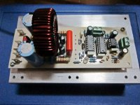
The schematic is already tested, I created an earlier version of it (attached pictures) however I only used +-51V for the supplies. I don't have a power supply with a higher voltage right now.
If anyone can confirm that the IRS1500 is working for +-75V and up then we can adapt the three inverter buffer stage to the schematic.
Attachments
I would like to buy some IRS2092, high power MOSFET, inductors. Can you please let me know where in India I can buy them, Culcatta/Banglaore preferred.
Or any online shop in India to check price and availability.
Thanks
Raj
Hi Raj,
you can prefer Bangalore.JP street(electronic street) everything you will get.
i am living in KERALA.(malayalam Naadu)
Regards
MANOJ
Hi stewin,
do not need for three inverter buffer stage(IRS900),when you apply high voltage the buffer and level shift(2n5401) should be aligned properly.i mean you change resistor collector and emitter side of 2n5401 then it will work(10K & 8K2)for higher voltage.
Regards
MANOJ
do not need for three inverter buffer stage(IRS900),when you apply high voltage the buffer and level shift(2n5401) should be aligned properly.i mean you change resistor collector and emitter side of 2n5401 then it will work(10K & 8K2)for higher voltage.
Regards
MANOJ
Hi Manojtm ,
Could you please start another topic for your design ? and if it's possible , move AUD600 related posts to that topic..
anyway , how can i have your amp's schematic ? because i want redesign board and change some component or their footprints etc.
do not use very low resistor like 10R for gate drive,(IR2110 will heat)safe run is 40R and not worried about THD (mackie using 47R for @450KHz)
i think that's because mackie use Class-d for LF drive..
Regards
Hi stewin,
do not need for three inverter buffer stage(IRS900),when you apply high voltage the buffer and level shift(2n5401) should be aligned properly.i mean you change resistor collector and emitter side of 2n5401 then it will work(10K & 8K2)for higher voltage.
Regards
MANOJ
thanks manoj GOD bless you .
i think that's because mackie use Class-d for LF drive..
Hi IR,
yes its LF i agree that but its drive MID also (MID BASS)
Regards
MANOJ
happy new year
pcb nice congratulations, good job. how much power rate (w), a query that design is Nanotechnology mo.
happy new year to all forum

The schematic is already tested, I created an earlier version of it (attached pictures) however I only used +-51V for the supplies. I don't have a power supply with a higher voltage right now.
If anyone can confirm that the IRS1500 is working for +-75V and up then we can adapt the three inverter buffer stage to the schematic.
pcb nice congratulations, good job. how much power rate (w), a query that design is Nanotechnology mo.
happy new year to all forum
Attachments
Smoke on my AUD600
Hi Manoj:
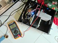
Yesterday I powered up my AUD600, Ver1.0. First I tested power board, DC rail was +-42 volt and found 12V DC with respect to GND at bias point.
Connected power to amp board without mounting any IC's and measured voltage, found 6.2 volts (Zener 6.3). TL071-072 had 6 volts of their VCC PINs.
It seemed that both the boards are okay and then I mounted all the IC's and connected all the power connection. Then I heard a pop noise and little smoke from NE555 IC area.
At the same time I saw smoke from IRF630 area (Power Board). There was a bulb (100W) in series with my transformer which flashed out in full. Drawing high current due to short circuit!!!
I measured bias voltage which is 29V with respect to GND, earlier this was 12V. Which part(s) may have been blown?
Can you please let me know which causing this problem? How to check the flaws of amp board? I did not attach those parts which are not recommended for first setup.
Waiting for your help.
Thanks
Raj
Hi Manoj:
Yesterday I powered up my AUD600, Ver1.0. First I tested power board, DC rail was +-42 volt and found 12V DC with respect to GND at bias point.
Connected power to amp board without mounting any IC's and measured voltage, found 6.2 volts (Zener 6.3). TL071-072 had 6 volts of their VCC PINs.
It seemed that both the boards are okay and then I mounted all the IC's and connected all the power connection. Then I heard a pop noise and little smoke from NE555 IC area.
At the same time I saw smoke from IRF630 area (Power Board). There was a bulb (100W) in series with my transformer which flashed out in full. Drawing high current due to short circuit!!!
I measured bias voltage which is 29V with respect to GND, earlier this was 12V. Which part(s) may have been blown?
Can you please let me know which causing this problem? How to check the flaws of amp board? I did not attach those parts which are not recommended for first setup.
Waiting for your help.
Thanks
Raj
Attachments
DC rail was +-42 volt and found 12V DC with respect to GND at bias point.
At the same time I saw smoke from IRF630 area (Power Board). There was a bulb (100W) in series with my transformer which flashed out in full. Drawing high current due to short circuit!!!
I measured bias voltage which is 29V with respect to GND, earlier this was 12V. Which part(s) may have been blown?
Hi Raj
BIAS 12v is with respect to -ve supply rail only not GND.Connect 3pin BIAS point to amp board 3 pin
POWER Board AMP PCB
PIN=+12v-------------- +12v
PIN=(S)OC ------------ (S) center PIN
PIN=(-75V)------------ -Ve PIN
Regards
MANOJ
Hi Raj
BIAS 12v is with respect to -ve supply rail only not GND.Connect 3pin BIAS point to amp board 3 pin
POWER Board AMP PCB
PIN=+12v-------------- +12v
PIN=(S)OC ------------ (S) center PIN
PIN=(-75V)------------ -Ve PIN
Regards
MANOJ
Thanks Manoj.
I will check and will inform you.
Last edited:
thanks to jlester87
HI
thanks for your sharing
why you and other engineer dont creat all things in one board ?
main board dont have OCP ?
for OCP i must creat protection board too ?
thanks
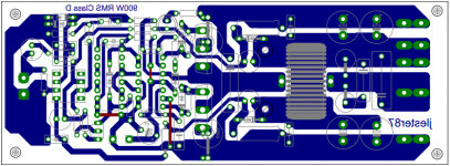
I'll gonna share my layout based on IRS900 / IRAUDAMP1.
I put the bias supply onboard and put an external OCP trigger so that the speaker protect will activate in case of short circuit.
Speaker protection circuit included.
Just don't remove my name when you etch the PCB. It gives me the credit for my effort.
Happy new year everyone
HI
thanks for your sharing
why you and other engineer dont creat all things in one board ?
main board dont have OCP ?
for OCP i must creat protection board too ?
thanks
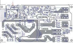
i dont like jumpers
I think this is beter
I think this is beter
An externally hosted image should be here but it was not working when we last tested it.
- Home
- Amplifiers
- Class D
- UCD 25 watts to 1200 watts using 2 mosfets