 .BTW the fets in your video are they irfp250 2pairs?
increase gate resistor with correct value , decrease temp.
-increases the switch times of the mosfets(rise & fall) - increases the deadtime - increases the THD .
")
For the subamp application it'll do , but for the full range......
Yea , at that freq you can bravely use 2-3 pairs of mosfets (4227)I use osc=125 KHz it is not BAD and filter 4th order one
What driver & mosfet?normally we are using osc=300 KHz for good THD Better for 500 KHz
And about THD - how much better ? maybe you'll post some ?
Hi CPX
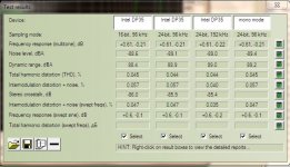
And my netbook has awful noise ~56dB and IMD ~0.5%
Can't find Acoustic Analyzing System 5E , can you share it with me?
My soundcard (built-in on motherboard Intel DP35) has such results (measured line-in-line-out) . I think they are not good enough for measurement?I am using RightMark Audio Analyzer 6.2.3(free version) and Acoustic Analyzing System 5E(THD only), they give similar results.
And my netbook has awful noise ~56dB and IMD ~0.5%
Can't find Acoustic Analyzing System 5E , can you share it with me?
Attachments
Hi don2007ksa
I think the best solution is the amp from this thread
http://www.diyaudio.com/forums/atta...tts-1200-watts-using-2-mosfets-ir2110_ucd.zip
Dimonis i have 60 hertz,+/- 90 VOLTS @ 800 watts power transformer,i'm going to used a 4 ohm's load around 700watt's full range speaker,thank's.
I think the best solution is the amp from this thread
http://www.diyaudio.com/forums/atta...tts-1200-watts-using-2-mosfets-ir2110_ucd.zip
I think the best solution is the amp from this thread
http://www.diyaudio.com/forums/attac...ir2110_ucd.zip
Hi dimonis
Self osc. UCD is not good for Higher WATT (above 200W).It will create lot of problems
ie. Heat,Noise & high Start up Current
Hi CPX
My soundcard (built-in on motherboard Intel DP35) has such results (measured line-in-line-out) . I think they are not good enough for measurement?
And my netbook has awful noise ~56dB and IMD ~0.5%
Can't find Acoustic Analyzing System 5E , can you share it with me?
Yes..your results are pretty bad
.Try decreasing output level a little(2,3 db) even if the software says volume to low in calibration windows .If the results are the same you can still test your amplifier by using substraction.Hi dimonis
Self osc. UCD is not good for Higher WATT (above 200W).It will create lot of problems
ie. Heat,Noise & high Start up Current
Why do you say that?A bad design will generate these problems not self osc ucd topology.
Why? The only reason you will get all those things is because of bad schematic or pcb design. Using an IRS20957 instead of a 2110 will get rid of those nasty level shifters, and allow a proper high-speed comparator running off +/-5v supplies. I have designed bridged self-oscillating amps, with fully-balanced input and modulator stages at significantly higher outputs than 200W.
from LM4651 & 4652 Notes .their test App. notes fsw=125KHzincreasing the switching frequency will reduce the THD but also decreases the efficiency
and maximum output power level before clipping. Increasing
the switching frequency increases the amount of loss because switching currents lower the efficiency across the output power range. A higher switching frequency also lowers
the maximum output power before clipping or the 1% THD
point occur.
BTW, my response was to the rather foolish statement by 'manojtm', not the sensible comment by 'CPX'!
This is not a foolish!!!!!!!!!!!!!!!!!!
you just tell me the Efficiency of your AMP
output imp. change your fsw
Including the fully-isolated dc-dc conversion stage to allow operation of the amplifer from a 24V dc supply (converts 24V to +/-85V together with the associated low-voltage supplies), I get over 82% efficiency at 120W out. Tested this morning at half-power on a 240W amplifier. (This is a low power amp, but it is one I'm working on at the moment).
So perhaps 94% eff for the amp stage and 87% for the isolated dc-dc stage. I'm sure that someone like Eva can do even better.
I design class-D amplifiers as my main work for a very well known international engineering corporation, so I don't expect to be lectured at by someone who thinks an LM311 is a good modulator comparator!
- Home
- Amplifiers
- Class D
- UCD 25 watts to 1200 watts using 2 mosfets