cant get
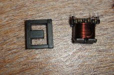
t106_2 core here so i cant really tell what core will sound best can any one suggest where i can order t106_2 prewound 33uh inductor
warm regards
andrew lebon
Amidon in the states have t106-2 core. I alos picked some up on ebay.
I just wind a couple of metres of 18swg enammeled copper wire around the core. Its a fiddle but isnt too bad.
thanks
Hi Stewin
greetings at last got it working dont have any issues on amp working
its playing great clear and powerful the pcb i posted looks bad its the first pcb on the thread after many failed attempts ifigured out how it should be assembled without blowing up parts trying to make a bridged version designing
the PCB will be a problem no PCB experience but ill try can you share any bridged schematics using IR2110 I will use IRFB4227 for outputs btw whats working frequency of this amp have you experimented with feedback 330pf
cap schematic says mica i have used 330pf ceramic 1kv i have 330pf silver mica
would changing the ceramic to silver mica make sound more clear not tried is as yet hope you can share your results
warm regards
andrew lebon
try to get e cores from old pc power supply and boil them in hot water . after separating them coil 30 turns and make sure you add 1mm gap using a tiny piece of old cd or dvd disc. .
A good thing , but the gap must be larger - something about 2mm , or 4mm in the center leg.
")
Attachments
FEEDBACK CAPACTOR 330pf
In the feedfack, try to change capacitor C1 (330p, mica) to 150p or 100p (you can use ceramiic or anything). This should turn your switching freq from 120kHz to about 200-230kHz. This would improve filtering from 20dB to about 30dB.
Hi
greetings will changing C1 330pf to 150 pf on 50 volts dc supply work on my ucd outputs IRF250N OTHERWISE all components are same as schematic given
by egtagle
warm regards
andrew lebon
A good thing , but the gap must be larger - something about 2mm , or 4mm in the center leg.
why large gap like 4mm
If you want 1000 W, then fsw should not exceed 200 kHz. Then L>40 uH is advisable to achieve low idle loss. Since 100V/3 ohm (current headroom needed!) = 33A, E>22 mJ. Energy density in gap at saturation is about 40 mJ/cm^3, so at least a half cm^3 is needed for this much power. A=1.2...1.5 cm^2, so d=4 mm is a good estimation. But leakage is horror! I use 4 mm also, but in EE55 (A=3.5cm^2, L=80 uH), so it's safe and perfectly cool.why large gap like 4mm
But for only 50 V and 4 ohm, 1 mm gap is OK!
Last edited:
Hi All
Now I will give my working design!!!!!!!!!!!!!!!
Its simple and good.Protection and all other things can added later
Hi Manoj:
Electronics is my hobby and mostly excited for amplifiers, I am trying to make a class D amp using your schematic. Now can you please tell me what is meant with (SD) sing (Pin 11 of IRS2110)? And can I find the inductors in the market?
Here is the link of PCB: https://www.cx.com/mycx/share/kBI-n1e0EeGJkxICOBs4YA/UCD_India.pcb
Not finished yet, need to improve tracks.
Thanks in advance.
Raj
Last edited:
bridging ucd amplifier
hello
greetings having built 2 channels sucessfully and using it at 50 volts dc supply just want to know if this amp can be bridged with external bridging circuit
please just finding my feet in D CLASS hoping for some help from all
warm regards
andrew lebon
hello
greetings having built 2 channels sucessfully and using it at 50 volts dc supply just want to know if this amp can be bridged with external bridging circuit
please just finding my feet in D CLASS hoping for some help from all
warm regards
andrew lebon
Ok..i nedd schematics.
But for straters these are the problems:
-very long path form ir2110 to fets.
-fets to far apart
-no fets snubers
-no ground plane and ground with loops and very long
-no local decoupling
I am sorry..but your board is VERY bad...DO NOT try to make it..use the authors board or my board for inspiration.
But for straters these are the problems:
-very long path form ir2110 to fets.
-fets to far apart
-no fets snubers
-no ground plane and ground with loops and very long
-no local decoupling
I am sorry
..but your board is VERY bad...DO NOT try to make it..use the authors board or my board for inspiration.Hi Manoj:
Electronics is my hobby and mostly excited for amplifiers, I am trying to make a class D amp using your schematic. Now can you please tell me what is meant with (SD) sing (Pin 11 of IRS2110)? And can I find the inductors in the market?
Here is the link of PCB: https://www.cx.com/mycx/share/kBI-n1e0EeGJkxICOBs4YA/UCD_India.pcb
Not finished yet, need to improve tracks.
Thanks in advance.
Raj
I got it CPX, no surprise for me, thanks for taking time to check and feebacks. will try to improve in future.
here is the schematic CPX; can you please gide me which PCB to use. I mean kindly share your one. Would be greatful...
Last edited:
- Home
- Amplifiers
- Class D
- UCD 25 watts to 1200 watts using 2 mosfets