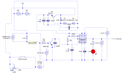
Because lower disipation of shunt resistor, I will use transistor instead of optocoupler. Now voltage drop is 0.7V
In simulator it works (schematic like Luka's)
Rsens = 0.7V / (Ucc/2Rload*2*sqrt2)
Rsens = 1.4Rload*sqrt2 / Ucc (1.4~sqrt2) =>
Rsens = sqrt2*Rload*sqrt2 / Ucc
finaly
Rsens = 2Rload/Ucc (=) Ohms
In simulator it works (schematic like Luka's)
Rsens = 0.7V / (Ucc/2Rload*2*sqrt2)
Rsens = 1.4Rload*sqrt2 / Ucc (1.4~sqrt2) =>
Rsens = sqrt2*Rload*sqrt2 / Ucc
finaly
Rsens = 2Rload/Ucc (=) Ohms
Attachments
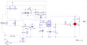
I made a mistake regarding my wire/inductor protection...using an inductor with a core with value>1uH is not recomanded because it will be too sensitive to noise...
Aditional residual filtering should be made elsewhere...thanks Pafi for clearing that up.....so a low inductance(<1uh) wound wire is recomanded..
Dzony988 use optocupler/level shifter for ir2110 sd pin and faster detection if you love your transistors..
Aditional residual filtering should be made elsewhere...thanks Pafi for clearing that up..
...so a low inductance(<1uh) wound wire is recomanded..Dzony988 use optocupler/level shifter for ir2110 sd pin and faster detection if you love your transistors..
I said optocoupler for comunication with ir2110...
With optocoupler for the detector yes you will have 1.0-1.1 volt drop..if you decide to use my protection i thing you will get away with 400mv drop but i do not think you will have the pacience to sort resistors and obtain minimum error...
With optocoupler for the detector yes you will have 1.0-1.1 volt drop..if you decide to use my protection i thing you will get away with 400mv drop but i do not think you will have the pacience to sort resistors and obtain minimum error...
Last edited:
Because lower disipation of shunt resistor, I will use transistor instead of optocoupler. Now voltage drop is 0.7V
In simulator it works (schematic like Luka's)
Rsens = 0.7V / (Ucc/2Rload*2*sqrt2)
Rsens = 1.4Rload*sqrt2 / Ucc (1.4~sqrt2) =>
Rsens = sqrt2*Rload*sqrt2 / Ucc
finaly
Rsens = 2Rload/Ucc (=) Ohms
Dzony, what software did you use for schematic capture ?
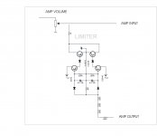
Do anyone have curcuit of input signal limiter but without optical elements. I try in simulator many of curcuit from google, but it doesnt work or has lot of distorsion.
something good what you used?
Reason why without opto elemets is because I dont like it and bigger rison is that I can only find photo resistor LDR07
Regards
something good what you used?
Reason why without opto elemets is because I dont like it and bigger rison is that I can only find photo resistor LDR07
Regards
You can use a led-photo resistor combination...
Have you simulated this? Fast Audio Peak Limiter (figure 2)
Have you simulated this? Fast Audio Peak Limiter (figure 2)
Do anyone have curcuit of input signal limiter but without optical elements. I try in simulator many of curcuit from google, but it doesnt work or has lot of distorsion.
something good what you used?
Reason why without opto elemets is because I dont like it and bigger rison is that I can only find photo resistor LDR07
Regards
try this its from APEX should working very well
Attachments
- Home
- Amplifiers
- Class D
- UCD 25 watts to 1200 watts using 2 mosfets