electroconico!
Probably the root of the problem is the slow body diode of IRFP250, but not alone. It can be combined with poor layout, insufficient decoupling, etc...
hi Pafi
I´m using bypass diode , mur120.
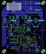
Maybe the layout

Attachments
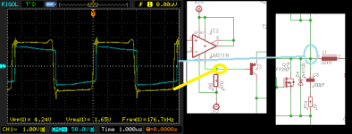
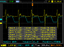
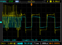
I have checked the oscillation on comparator output and mosfet output(Input to Inductor).
It works great at low volume even with air core.
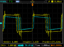
The problem comes out when I set the volume hi as 0.8Vpp.
The oscillation goes wrong , on comparator output pin the signal has gone up to 900KHz and it isn´t square,if I turn down the volume the signal looks good again.
I did a double check in feedback stage,all looks good.(Components values,etc..)
What could be the problem ?
Noise ??
the lm311?
-------------------
Pics below :
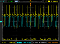
-Oscillating without input signal.
-Oscillating with input ignal 1KHz less than 0.5vpp
-Comparator output error if I set the volume close to 1vpp.
-Comparator out zoom.
-Turning down the volume the signal looks good again.
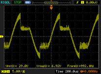
-Output Signal after inductor, the problem occurs at same level like 30VRMS(inductor 33uH,22uH,air core).
regards!!
It works great at low volume even with air core.
The problem comes out when I set the volume hi as 0.8Vpp.
The oscillation goes wrong , on comparator output pin the signal has gone up to 900KHz and it isn´t square,if I turn down the volume the signal looks good again.
I did a double check in feedback stage,all looks good.(Components values,etc..)
What could be the problem ?
Noise ??
the lm311?
-------------------
Pics below :
-Oscillating without input signal.
-Oscillating with input ignal 1KHz less than 0.5vpp
-Comparator output error if I set the volume close to 1vpp.
-Comparator out zoom.
-Turning down the volume the signal looks good again.
-Output Signal after inductor, the problem occurs at same level like 30VRMS(inductor 33uH,22uH,air core).
regards!!
Attachments
-
 Oscilando sin señal.png14.4 KB · Views: 1,606
 -
 Oscilando 1KHz input bajo volumen.png8.5 KB · Views: 1,429
 -
 Oscilando incremento volumen 1vpp.png9 KB · Views: 1,397
 -
 Error salida comparador.png17.1 KB · Views: 1,369
 -
 Oscilación 1vpp bajando volumen..png9.3 KB · Views: 202
 -
 senal de salida nucleo aire.png7.7 KB · Views: 190
Last edited:
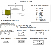
This is multilayer air core inductor, with dimensions is very small.
Maybe we can use it, what do you think?
I posted example on pisture for 20uH and 1.5mm wire (dimater is 1,5mm)
If you use other diametar of wire all dimensions will change, then use formulas
R = 0.026 ohm
Maybe we can use it, what do you think?
I posted example on pisture for 20uH and 1.5mm wire (dimater is 1,5mm)
If you use other diametar of wire all dimensions will change, then use formulas
R = 0.026 ohm
Attachments
Last edited:
Fuse itself is stupid. Fast blowing fuse is stupider.
Useing fuse for overcurrent protection is not a go. Music signal is peaky, load is variant (if you have a nominal 4 Ohm load, that can be even 2 Ohm at impedance minimum - bandbass cabinets and tapped horns usually), so you have to put in much larger fuses than needed (if you plan a 400W @ 4 ohm amp, you need to put in >20A fast blowing fuses not to false trigger), than it even won't protect at a slight short. Fuse will go weak form start-on current of caps, and from high peak currents, and it will fail with time, even when there is no overcurrent or short circuit.
Useing crowbar protection with normal or slow blowing fuses rated properly (not to false trigger), is a way to go.

 you are estupid you look estupid
This is multilayer air core inductor, with dimensions is very small.
Maybe we can use it, what do you think?
...
There are some problem with it:
- It radiates more magnetic field than any other inductor.
- With solid wire it will get very hot. Litz wire is a must!
Originally Posted by lorylaci
Fuse itself is stupid. Fast blowing fuse is stupider.
Useing fuse for overcurrent protection is not a go. Music signal is peaky, load is variant (if you have a nominal 4 Ohm load, that can be even 2 Ohm at impedance minimum - bandbass cabinets and tapped horns usually), so you have to put in much larger fuses than needed (if you plan a 400W @ 4 ohm amp, you need to put in >20A fast blowing fuses not to false trigger), than it even won't protect at a slight short. Fuse will go weak form start-on current of caps, and from high peak currents, and it will fail with time, even when there is no overcurrent or short circuit.
Useing crowbar protection with normal or slow blowing fuses rated properly (not to false trigger), is a way to go.
Pedro lolz what happened, why is lorylaci an estupid?
Last edited:
It's been a long time, I haven't been here. I try to answer some questions people asked me:
- DZONY: Changing swithcing freq to 400kHz can be really hard. First you would need a faster comparator. But 400kHz needs very fast FETS to. If you increase the switching freq but with the same prop. delay, the output distortion can rise at lower power levels, due to modulation error! For an IRFP250N >250kHz is a no go... (mybe with some IRFB4227 hmmm )
- All people favorising air cores: Air cores radiate a much! They are lossy. Even when they are colder then other inductors, they can have more losses! (why? heat is spearated to a large volume, and the cooling area is much bigger). Due to losses are mostly copper losses, and wire is long, you need stranded wire or litz! The AC resistance can be much more then DC resistance (due to skin effect). You even not thought about parasitic capacitances. In a good designe toroid inductor there is only one layer, and a sufficient start-end gap, this minimises parasitic capacitances, thus increasing filtering at very high frequencies, where a multilayer air core inductor would be seen as a inductor with a big parralel capacitance.
- pedro: Why am I stupid? Fuse can not be an efficient and reliable over-current protection at power amps.
- electronico: you inductor is still no good one. Due to your relatively low switching freq, you need at least 30uH (rule of a thumb: swithcing freq should be about a decade higher than corner freq...). Get some proper material, like T130-2 or T157-2, check it here: Toroids, Ferrites, Parts, Kits, Toroid King, QRP Erector Set, I am sure they ship to Mexico, or get some gapped ferrites. You can take apart transformers from SMPSs by cooking them in water, they are usually gapped, with increased gap, you could build a good inductor. Last weekend I cooked "transformer-soup" for an hour, the reward was a dosen of ETD cores. You could also check supply ripple at the legs of the fets for proper decoupling.
- uglykid: yes it can be bridged. It also increases reliability due to end of bus pumping. Then it is called full-bridge. The hardwire redesing of the amp to full-bridge can also eliminate the need of level-shift, and can have a lot of benefits.
- DZONY: Changing swithcing freq to 400kHz can be really hard. First you would need a faster comparator. But 400kHz needs very fast FETS to. If you increase the switching freq but with the same prop. delay, the output distortion can rise at lower power levels, due to modulation error! For an IRFP250N >250kHz is a no go... (mybe with some IRFB4227 hmmm
)- All people favorising air cores: Air cores radiate a much! They are lossy. Even when they are colder then other inductors, they can have more losses! (why? heat is spearated to a large volume, and the cooling area is much bigger). Due to losses are mostly copper losses, and wire is long, you need stranded wire or litz! The AC resistance can be much more then DC resistance (due to skin effect). You even not thought about parasitic capacitances. In a good designe toroid inductor there is only one layer, and a sufficient start-end gap, this minimises parasitic capacitances, thus increasing filtering at very high frequencies, where a multilayer air core inductor would be seen as a inductor with a big parralel capacitance.
- pedro: Why am I stupid? Fuse can not be an efficient and reliable over-current protection at power amps.
- electronico: you inductor is still no good one. Due to your relatively low switching freq, you need at least 30uH (rule of a thumb: swithcing freq should be about a decade higher than corner freq...). Get some proper material, like T130-2 or T157-2, check it here: Toroids, Ferrites, Parts, Kits, Toroid King, QRP Erector Set, I am sure they ship to Mexico, or get some gapped ferrites. You can take apart transformers from SMPSs by cooking them in water, they are usually gapped, with increased gap, you could build a good inductor. Last weekend I cooked "transformer-soup" for an hour, the reward was a dosen of ETD cores. You could also check supply ripple at the legs of the fets for proper decoupling.
- uglykid: yes it can be bridged. It also increases reliability due to end of bus pumping. Then it is called full-bridge. The hardwire redesing of the amp to full-bridge can also eliminate the need of level-shift, and can have a lot of benefits.
hi guys
hi lory
the air core inductors are good choice for most fans of this project, and you answered that the air core inductors is a stupid idea is stupid that is all for you ?????
fuses to prevent fire as no current limit according to your own is a stupid idea??
I should not comment with bad words
that will make you look stupid
best regards
peter
Air coils are big, ineffective, and radiate noise.
Because they are big they were able to dissipate the loss because of the high current (because of low switching freq).
Since this is an UcD amp, the feedback is after inductor, so every non-linearitiy of the inductor is compensated by the feedback. Gapped ferrites also very linear until 80% of saturation. Iron-powder cores are less linear.
So chosing air-core inductor for linearity is stupid. I think they chose it because any other could not dissipate, mainly because the low switching freq. A bad solution for a bad choice.
hi lory
the air core inductors are good choice for most fans of this project, and you answered that the air core inductors is a stupid idea is stupid that is all for you ?????
fuses to prevent fire as no current limit according to your own is a stupid idea??
I should not comment with bad words
that will make you look stupid
best regards
peter
I think it is wrong to call someone stupid if someone expressed his opinion, after all we are all here because of communication, build an amplifiers and a kind of coming together.
In conjunction with air coils, theory and practice show better performance for amplifiers who use a inductor with core of specialized materials for class D, and many comercial amps use them. Air cores are more linear and good for small inductors in serial with output at class AB, radio technic and speakers passive crossover.
Otherwise, my JBL and Yamaha 15" (hi class) speakres for crossover dont use air cores, but use some material cores (i dont know what is it, ferrite or micormetals..)
lori
do not confuse people all know that the best inductor is the air core, 30 turns of 12 awg wire cal has a very low dc resistance, and diameter of over an inch capacitance is minimal, I remember that it is a international forum and not everyone can get Micrometals inductors or similar
and use in tests of air core inductor is ideal.
the best option is this http://www.sagami-elec.co.jp/file/7g31a.pdf if it inductors
Like a couple of STW34NB20 work more than 650 kHz for high fidelity fans that if the dead time less than 25 ns
saludos desde Mexico
Pedro!
A core is not an inductor. Air core can be good, if you want to build an induction heater, or antenne.
Forget about low DC resistance, it's not really important! Any resistance below 0.01*Rload (40 mohm at 4 ohms load) is perfect!
What is more important is Q factor at switching freq, and this is quite low for a multilayer air core inductor made of solid wire. The reason: magnetic field doesn't stay inside the "core", it penetrates into the wires as well, causing eddy currents. The density of this eddy current can be (and will be) much higher than the idle ripple current density, because it is induced by many turns.
And of course the opened inductor radiates very much EMI.
Capacitance can be low or high depending on the winding scheme and insulator type/thickness. (This also applies to any other cores.)
You wrote too many sentences I cannot understand:
In what tests? In what aspects? Compared to what other inductors?
But you are right, saying some idea is stupid is not a polite/clever behaviour.
A core is not an inductor. Air core can be good, if you want to build an induction heater, or antenne.
Forget about low DC resistance, it's not really important! Any resistance below 0.01*Rload (40 mohm at 4 ohms load) is perfect!
What is more important is Q factor at switching freq, and this is quite low for a multilayer air core inductor made of solid wire. The reason: magnetic field doesn't stay inside the "core", it penetrates into the wires as well, causing eddy currents. The density of this eddy current can be (and will be) much higher than the idle ripple current density, because it is induced by many turns.
And of course the opened inductor radiates very much EMI.
Capacitance can be low or high depending on the winding scheme and insulator type/thickness. (This also applies to any other cores.)
You wrote too many sentences I cannot understand:
Besides inproper grammar I still cannot understand:and use in tests of air core inductor is ideal.
In what tests? In what aspects? Compared to what other inductors?
Best? You said air core is ideal! This is a shielded inductor!the best option is this
Does anybody understands this?...if it inductors
I can't decode this. What is the connection between these things?Like a couple of STW34NB20 work more than 650 kHz for high fidelity fans that if the dead time less than 25 ns
But you are right, saying some idea is stupid is not a polite/clever behaviour.
Last edited:
Hi my first class D amp is working
1. but Inductor is very very hot and cooking
have make some test with different inductors
30 uh und 50 uh all the same ...cooking very heat and some high frequency noise
Does somebody have solution to remove noise ( its like noise from FM radio staion if signal is very bad) and cooking inductors heat
mosfets are warm.
2. today evening have test with inductor from defective PA class D amp, but with this inductor Mosfets cooking and inductor is only warm, noise is about 80 % gone but now I have another noise, it sounds like 19 KHZ Stereo carrier signal from FM radio station and Im surprised, 1,5 uf polyester capacitor after inductor is very warm with this inductor, ir 2110 is much more warm with this inductor too
I have add in my design all improvements from this forum like 1 NF in input stage and 100 uf to remove dc
and.... 100 pf with 22k to increase switching frequency compare to 330 pf in original design
have no idea to solve my problems
Last edited:
Hi my first class D amp is working
1. but Inductor is very very hot and cooking
have make some test with different inductors
30 uh und 50 uh all the same ...cooking very heat and some high frequency noise
You need to use a micrometals core.
t106-2 with a couple of meters of 18swg enamelled copper wire.
Ebay sells them in one offs.
For 2 cores i don`t know how to, but with 1 core you 15 turns
An externally hosted image should be here but it was not working when we last tested it.
where can i get this induction calculator soft...google nothings find v1.03a
Hi my first class D amp is working
1. but Inductor is very very hot and cooking
have make some test with different inductors
30 uh und 50 uh all the same ...cooking very heat and some high frequency noise
Does somebody have solution to remove noise ( its like noise from FM radio staion if signal is very bad) and cooking inductors heat
mosfets are warm.
2. today evening have test with inductor from defective PA class D amp, but with this inductor Mosfets cooking and inductor is only warm, noise is about 80 % gone but now I have another noise, it sounds like 19 KHZ Stereo carrier signal from FM radio station and Im surprised, 1,5 uf polyester capacitor after inductor is very warm with this inductor, ir 2110 is much more warm with this inductor too
I have add in my design all improvements from this forum like 1 NF in input stage and 100 uf to remove dc
and.... 100 pf with 22k to increase switching frequency compare to 330 pf in original design
have no idea to solve my problems
The inductor from class d amp may be a good choice.
Polyester capacitor is not suitable for this application. You should see its datasheet. Check for dissiaption factor. In a WIMA catalog PET (poly(ethyleneterephtalate) a polyester type) has 3% dissipation factor at 100kHz (increasing at higher freqs), while a polypropylene has 0,25% at 100kHz. So you should get some PP capacatior intended for high-frequency use, read the datasheet first carefully.
What is your switching freq? Scope pictures?
- Home
- Amplifiers
- Class D
- UCD 25 watts to 1200 watts using 2 mosfets