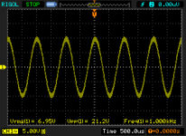
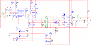
This is my first prototype of UCD. 400W/4ohm sin @ +-60V
Nice PCB
")
----------------------------------------------------------------------
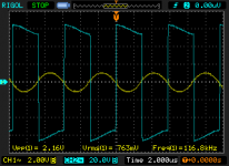
Testing my prototype at +-60 vdc .
Input Signal at 1KHz , less than 1Vpp.
I got these results.
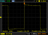
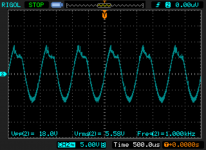
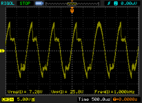
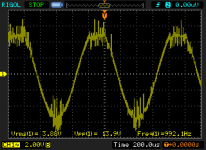
Before the inductor I´m getting a nice square signal,after the inductor i dont know why the signal it´s like cutted/. I got less tha 5W
What do you think?
a inductor problem?,high side mosfet driver problem?
ty
Attachments
Last edited:
Nice PCB
----------------------------------------------------------------------
Testing my prototype at +-60 vdc .
Input Signal at 1KHz , less than 1Vpp.
I got these results.
Before the inductor I´m getting a nice square signal,after the inductor i dont know why the signal it´s like cutted/. I got less tha 5W
What do you think?
a inductor problem?,high side mosfet driver problem?
ty
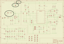
Hello, try change these components. R5 change amplifier gain and R9, C17 change oscilation frequency to 250Khz.
Attachments
@fibko
For modern fets with fast diode (or older like IRFP250N +bypass with MUR120) you can change gate resistor from 27Rto 22R for better gate charge and C15 to 100uF for beter reproduction of low frequency because 47uf is lower limit in feedback for low frequency (like 70Hz or lower)
Do you measure swich freq with this satup? Do you exceed 240KHz without noice?
@fibko
For modern fets with fast diode (or older like IRFP250N +bypass with MUR120) you can change gate resistor from 27Rto 22R for better gate charge and C15 to 100uF for beter reproduction of low frequency because 47uf is lower limit in feedback for low frequency (like 70Hz or lower)
Do you measure swich freq with this satup? Do you exceed 240KHz without noice?
Amplifier run approximately on 250Khz with small noise. How I can start oscillate amplifier without signal? Because when I turn on, amplifier not oscillate.
@fibko
For modern fets with fast diode (or older like IRFP250N +bypass with MUR120) you can change gate resistor from 27Rto 22R for better gate charge and C15 to 100uF for beter reproduction of low frequency because 47uf is lower limit in feedback for low frequency (like 70Hz or lower)
Do you measure swich freq with this satup? Do you exceed 240KHz without noice?
Can I change gate resistor to 22R with 1N4148 bypass diode?
well yes, 4148, 4448 and such diode work great, ultra fastCan I change gate resistor to 22R with 1N4148 bypass diode?
while they are not any high current ones, they are great pulse diodes, since gates are discharged fast and in short time
Its also should be WANTED to use fets not like 250's, but the ones with small gate capacitance and so on, those are much better on audio and in working of the amp itself

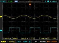
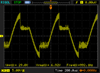
I used a 100pF cap instead 330pF.
Mosfet irfp250N with bypass dione mur120.
Power supply +-60vdc
Input signal less than 0.6vpp
Is it a saturation problem ??
I can't go up more than that.
When I removed 1u capacitors, I have the same problem. I thing this capacitors are very interesting for stability and I add 1000u and 100n
does the coil get hot?
why do you use such small signal?
The inductor it´s cold.
That is the signal level that it can use before to get the saturation.
When I removed 1u capacitors, I have the same problem. I thing this capacitors are very interesting for stability and I add 1000u and 100n
I have the 1uF capacitors. I´ll add the 1000uF caps to watch if something could change.
Later I´ll try other inductor .
ty
Last edited:
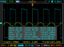
Well, I changed the toroid core .
Now i can get more power , a little more.
Toroid core 22uH . It is getting hot quickly.
The output looks very clean . Now the oscillation goes up to 230KHz.
I got the saturation at more high level than before.
So I think the problem is the toroid core.
What do you think ?
Pics below :
Old inductor.
New inductor before sat.
New inductor Sat.
Oscillation and output.
Oscillation
Attachments
Last edited:
And something else.So I think the problem is the toroid core.
But you didn't tell enough/any informations about neither the old nor the new core. Also the load is unknown.
I don't see any sign of saturation.
Did anyone test amp with T130-2 or T106-2 with 20-22uH?
I have an experience with T157-2, it works very well. At the same power rail ,others is get hot quickly.
And something else.
But you didn't tell enough/any informations about neither the old nor the new core. Also the load is unknown.
I don't see any sign of saturation.
5 ohms load.
inductor
How does it should look ?
The mosfets still cold.
------------------------------------
At my firts try I built 200W@4 ohms amp
Power supply = 40Vdc
It did not go to distorsion also the volume wasn´t set to full, but the output signal started to look like the pics showed , and a sound came out like sss ssss sssSS ss.
We got almost 130W
Last edited:
Hi guys, i want try this amp, i saw the original file of this amp and the post before this saying there is a much better ways to do the pcb and some improves on the circuit.
I anyone can tellme which board i should use and modifications on the circut, i dont want protections just the amp but whit the improves that u guys just make.
Ty and sry for my english, im working on it xD
I anyone can tellme which board i should use and modifications on the circut, i dont want protections just the amp but whit the improves that u guys just make.
Ty and sry for my english, im working on it xD
And something else.
But you didn't tell enough/any informations about neither the old nor the new core. Also the load is unknown.
I don't see any sign of saturation.
You are right , I have changed the core coil to air core and i had the same result almost at the same rate VRMS 29vrms.
So , the problem is in other place , I´ll check comparator output,Hin -Lin inputs and mosfet gate signals.
Any suggestion??
ty!
Attachments
- Home
- Amplifiers
- Class D
- UCD 25 watts to 1200 watts using 2 mosfets