I have followed your suggestion. DC offset is OK. Noise is less without any connection at input. But when I just connected CD in but did not play any song, these is noise.Why?
Do you use a shielded cable? Unshielded cable will pick up noise.
Look for earth loops too, because it will pick up every radioation from the board or output coil. Connect common to safety earth pole on the AC plug.
Maybe is a cable, try to short input and gnd without cable direct on pcb, you must not have any noise if everuthing is ok. If ypu have, look up at conections on input and output fets. I didnt try with 1nF on input, I try with 4.7n and 100p in paralel just like in previous desing
Overload protection without shunt res.
Hi to all
One good engineer from my country was recommended to me cheap and very good solution for overload protection without SHUNT resistor. He used this schmatic many times (for 30 years) and this is good because can use with any amplifier including this.
Actually its electronic fuse, very fast and stable and good because it has trim pot for setting current when amplifier will shut down.
Look at the schematic and read the word document that I atached. I belive you can understand because I use google translate from serbian to english.
What are you think?
Regards
Attachments
Maybe is a cable, try to short input and gnd without cable direct on pcb, you must not have any noise if everuthing is ok. If ypu have, look up at conections on input and output fets. I didnt try with 1nF on input, I try with 4.7n and 100p in paralel just like in previous desing
I short input to ground noise is less but still noticeable. And I use shielded input cable.So cable is not a problem.
Hi to all
One good engineer from my country was recommended to me cheap and very good solution for overload protection without SHUNT resistor. He used this schmatic many times (for 30 years) and this is good because can use with any amplifier including this.
Actually its electronic fuse, very fast and stable and good because it has trim pot for setting current when amplifier will shut down.
Look at the schematic and read the word document that I atached. I belive you can understand because I use google translate from serbian to english.
What are you think?
Regards
"without shunt resistor" ???
There is a 0,3 Ohm + transistor shunt in your schematic.
It will dissipate more than a simple 0,033 Ohm shunt (for 20A current sense).
So this idea is idiotic. You can do better with only a shunt and 2 transistors per side.
I short input to ground noise is less but still noticeable. And I use shielded input cable.So cable is not a problem.
Could you post pictures of your setup? (and about the layout too)
An externally hosted image should be here but it was not working when we last tested it.
Here is my idea to decrease shunt dissipation. Current treshold can be set by the trimpot. By using a JFET the voltage need at shunt resistor is decreased (from 0,6-0,7V, to <0,2V), so as dissipation.
So,for electronic end led its need 12V. J1 is short curcuit and J2 conect to SD pin. SD pin goes directly to J2 or have something with Ucc-. Did you test this. If you didint, i want to test this on my amp.
What about with voltage to gate of BF and conections to Udd and Ucc- ?
What about with voltage to gate of BF and conections to Udd and Ucc- ?
So,for electronic end led its need 12V. J1 is short curcuit and J2 conect to SD pin. SD pin goes directly to J2 or have something with Ucc-. Did you test this. If you didint, i want to test this on my amp.
What about with voltage to gate of BF and conections to Udd and Ucc- ?
The 12V supply is all referenced to the auxiliary supply of the IR2110. So the ground in this schematic goes to negative supply, SD pin is the SD pin of IR2110.
I haven't tested this, I've only simulated it.
Could you post pictures of your setup? (and about the layout too)
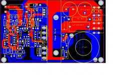
Here you are. Please comment.
Attachments
Here you are. Please comment.
Why do you think everyone uses the same layout editor as you?
If you want help post things as, so we can help.
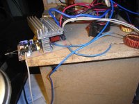
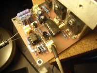
Please post pictures about your setup. (the module you built, with supplies... connected) I find my ask trivial, cause the problem is sure be there, then we can tell what.
Why do you think everyone uses the same layout editor as you?
If you want help post things as, so we can help.
Please post pictures about your setup. (the module you built, with supplies... connected) I find my ask trivial, cause the problem is sure be there, then we can tell what.
This is my module. With +-42VDC .All on the heat sink is warm. Coil is cool.
Attachments
Hi Opor,can you convert the PCB file to PDF? for toner transfer please
or tell me the program to open the pcb
Thank You
Protel99SE program can open this PCB.
- Home
- Amplifiers
- Class D
- UCD 25 watts to 1200 watts using 2 mosfets