@Laci
Laci I need your help!
I need for tomorow evening amplifier urgently(+-70V). I found ferrite core (on the picture) with this dimensions, I dont know what is it and material number but very carefully with grinder I maked 2x1mm gap, and now I have 2mm gap and on exaple picture I drew how i want to put the wire.
I dont know how meny turns that i need for 20-22uH. Pleas help.
Thank you
Since core is unknown, you need to measure it. Put a probe winding of few turns of any wire, then meausre inductance. Then calculate back Al from L=Al*n^2 (where n is turns). Then from the calculated Al, calculate the sufficient number of turns. If the calculated number of turns is less then 15 turns for this core, then your gap might be not enough, and it might saturate at high power.
Still UCD
My dears
Thanks by explanation
Yesterday i read another messages in the "source" called forosdeelctronica.
Many builders has very difficults to build (and work) this PWM amplifier.
I 'll try use the original layout.
I have two power supplies: a transfomer + 04 1N5402 diodes + two caps. 4.700uF/63V (+46/-46VDC) and a SMPS +40/-40VDC.
About the big 27R gate resistors I use it because I don't find 1/4W, only 22R.
I 'll connect series resistors in the rails for safe switch on.
Finally... why burn the 2N5401? Maybe some stay switch ON togheter? I don't understand this.
Thanks for all.
Sandro
You are mistaken...
This is an UcD amp, so if you take IR2110 out there should not be oscillation, so there is no PWM at LM311 output. That's not a PWM you are talking about, thats only the compared signal, it has nothing to do with PWM. Check it with an oscilloscope, it wont be at arond n*100kHz.
Connect the two main supply lines to the board with 20-100 Ohm 5W resistor (i use 47 Ohm 5W for this), it willl protect the fets in case of cross-conduction.
What is you supply voltage?
I'd also improve the PCB design, yours is far from optimal, even the original PCB design is better.
And why are you using 5W resistors for gate drive? 0,25W should be enough, and they seems to be wire-wound resistors (with high parasitic inductances), change them to cheap carbon film or metal film at once!
My dears
Thanks by explanation
Yesterday i read another messages in the "source" called forosdeelctronica.
Many builders has very difficults to build (and work) this PWM amplifier.
I 'll try use the original layout.
I have two power supplies: a transfomer + 04 1N5402 diodes + two caps. 4.700uF/63V (+46/-46VDC) and a SMPS +40/-40VDC.
About the big 27R gate resistors I use it because I don't find 1/4W, only 22R.
I 'll connect series resistors in the rails for safe switch on.
Finally... why burn the 2N5401? Maybe some stay switch ON togheter? I don't understand this.
Thanks for all.
Sandro
That is it cliping indicator from esp schematic. 3V form rail voltage. Tall me luka, can d class amp produce uncliped AC signal above power rails?
There is no point making such a punctual clipping indicator. THD+N rises before reaching supply rails because modulation limit. When modulation factor goes over 80% or below 20%, pulse times becomes very short, minimum pulse time is limited by propagation delay. Since it cannot be shorter then propagation delay, modulation error happens. (here to carrier signal changes, the original carrier frequency dissapears) Due to high feedback output remains good usually, but THD rises over this point, due to modulation error.
An externally hosted image should be here but it was not working when we last tested it.
My dears
Thanks by explanation
Yesterday i read another messages in the "source" called forosdeelctronica.
Many builders has very difficults to build (and work) this PWM amplifier.
I 'll try use the original layout.
I have two power supplies: a transfomer + 04 1N5402 diodes + two caps. 4.700uF/63V (+46/-46VDC) and a SMPS +40/-40VDC.
About the big 27R gate resistors I use it because I don't find 1/4W, only 22R.
I 'll connect series resistors in the rails for safe switch on.
Finally... why burn the 2N5401? Maybe some stay switch ON togheter? I don't understand this.
Thanks for all.
Sandro
If somebody does not understand class-d technique, SMPS technology, and switching converters im algemeniem, then he will have difficulties building this.
For a linear amp 27r wirewound or metalfilm does not count, here it can ruin your FET driving...
There are lots of bad things in your setup. Concentrate on making a satisfiing setup, instead of quessing what caused burning one stuff in a very bad setup. The original layout is much better then yours, try that one first.
I found ferrite core (on the picture) with this dimensions,...
I dont know how meny turns that i need for 20-22uH. Pleas help.
AL=70 approximately, so 18 turns should be OK.
AL~A/d*mu0
Thank you pafi. I measured 19turns. thats it. ")
But accidentally i found ETD29 core with gap 2x0.5mm gap, from PC smps. Do someone know materia nuber (27 or 87). how can i calculate number of turns.
From datasheet I see that N27 has variant with only 0.1mm gap on one half of core, and N87 has variant with 0.5mm (one half) gap and Al value is 201nH.
That means from calculation 10 turns for 20uH, or what. Is that calculation for one half or all core?
How many number of turns for whole core. One galf gas 0.5mm gap and whole core has 1mm
Thank you
Is that calculation for one half or all core?
The datasheet says:
"The AL value in the table applies to a core set comprising one ungapped core (dimension g = 0) and one gapped core (dimension g > 0)."
Thank you pafi. I measured 19turns. thats it.
But accidentally i found ETD29 core with gap 2x0.5mm gap, from PC smps. Do someone know materia nuber (27 or 87). how can i calculate number of turns.
From datasheet I see that N27 has variant with only 0.1mm gap on one half of core, and N87 has variant with 0.5mm (one half) gap and Al value is 201nH.
That means from calculation 10 turns for 20uH, or what. Is that calculation for one half or all core?
How many number of turns for whole core. One galf gas 0.5mm gap and whole core has 1mm
Thank you
The maximum reccomended frequency for N27 is 100kHz, N87 can take up to 300kHz, so its much better.
2x0,5mm gap is not enough, as you can see the required turns is not enough, it might saturate. Wind it with 18 turns, and put paper between the two half cores, until its inductance decreases to 20uH.
Attached there is a zipped spreadsheet to calculate cores.
Attachments
The maximum reccomended frequency for N27 is 100kHz, N87 can take up to 300kHz, so its much better.
N27 is perfectly usable for output filter inductor, since most of the current is in the audio band. The ripple current is too low to make any problem in a properly sized core. Those freq limits are only guidelines for pure HF excitation (SMPS transformer).
2x0,5mm gap is not enough, as you can see the required turns is not enough, it might saturate.
For 1 kW it's not enough indeed, but I don't know if he wants to build such a big amplifier or a smaller one. Basically the ETD29 is not enough for this high power, regardless of gap height.
Attached there is a zipped spreadsheet to calculate cores.
"Utáp" (Vcc) is a little too high, 150 V would be enough for 2 kW.
To the users: Attention! K1 and K2 are also from datasheet, they are different for different cores!
Last edited:
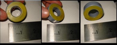
What material could it be this toroid ?
I want to use it but i dont have any specification.
any sugestion??
Color gray-yellow.
External diameter = 1 1/5" (1.5inches) - 38.1mm
Internal diameter = 13/16" (0.8125inches) - 20mm
wide = 9/16" (0.5625inches) - 14.28mm
-images atached
regards!
I want to use it but i dont have any specification.
any sugestion??
Color gray-yellow.
External diameter = 1 1/5" (1.5inches) - 38.1mm
Internal diameter = 13/16" (0.8125inches) - 20mm
wide = 9/16" (0.5625inches) - 14.28mm
-images atached
regards!
Attachments
What material could it be this toroid ?
I want to use it but i dont have any specification.
any sugestion??
Color gray-yellow.
[...]
regards!
I guess it's ferrite. You should measure AL!
If you don't have inductance meter, there are many other ways! You have to find some AC voltage source with a few kHz output (for example your sound card), put a resistor (for example 100 ohm) in series, attach the coil with 10...30 turns, and measure the voltage accross the coil (again, with your sound card input, and some SW)! You have to chose/altern such resistor/number of turns/freq so that Vcoil=0.02...0.3*Vsource!
You can differentiate between ferrite and metal powder with a very simple test: wind 20 turns, and put it in series with your regularly used tweeter (4 or 8 ohms, dinamic type!). If high tones are almost completely gone, then it's ferrite, if highs only slightly decreased, then it's metal powder. In the second case you can try to use it. In the first case first you need to break it into 2 or 4 pieces in order to avoid saturation!
An other way to differentiate between ferrite and metal powder: try to saw it! If you can do it easily, then it's not ferrite.
Last edited:
Hi to all.
During holidays, during party,my d class amps (3 of them, stereo) are worked 9 hours without stoping on full power, and survived all of them. Cold heatsinks, all components except resistors for TIP41 and LM311.
One of them is on +-60V with IRFP240 and it was worked on 2ohm load per chanel all the time. Transistors are survived although I thought it would not to submit 2 ohm load for a long time at full power..
Yesterday my firend told me the main problem: "you have pin 1 on gnd, so your comp output swings between 0 and 3V, not enoguh to turn on the transistors next to". I put pin 1 to -3V. Now everything works. With some setups my switching frequency reached 400kHz. But now I use the following schematic as a test:
An externally hosted image should be here but it was not working when we last tested it.
The switching freq is at 320kHz (3,1us periodic time). (the same feedback with other connecntiion was at 250kHz)
Following this schematic. Is noise eliminated?
Following this schematic. Is noise eliminated?
I had only probelem with noise in the first prototypes. So far I had no problem with noise. But noise mainly depend on your layout and connection, in my setup its eliminated.
I had only probelem with noise in the first prototypes. So far I had no problem with noise. But noise mainly depend on your layout and connection, in my setup its eliminated.
And how about DC offset?
And how about DC offset?
DC offset is easily eliminated if you put a 10uF cap in series with the 820r resistor. I don't care about a small DC offset (one of my board it was 0,2V, in some other it was 70mV, with the cap it is less than 50mV), and there are hundred ways to correct DC offset, so I don't know why everybody is so upset about it.
- Home
- Amplifiers
- Class D
- UCD 25 watts to 1200 watts using 2 mosfets