norazmi!
, and place Rg between emitter and base!
sorry... Im beginner what is Rg ?
norazmi!
only the discharge needs to be made faster. Connect base to IR2110, collector to source, emitter to gate, and place Rg between emitter and base!
Hi Pafi
Im beginner and a little confused how to do mit BC327...
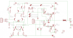
please check schematic..... is this ok or wrong ?
could you assist me ?
regards
Attachments
Hi Pafi
Im beginner and a little confused how to do mit BC327...
please check schematic..... is this ok or wrong ?
could you assist me ?
regards
The connection of the BC237s is OK, but you must erase D4 and D3.
By the way, do not use IRFP250N, the BC237 will make them discharge faster, but their body diodes are still very bad, so you don't really increase performance
(maybe you make it worse: this extra will make them switch faster, faster switching means higher dI/dt, so will mean more diode loss!)
Pafi's trick is appropiate for FETs with low Rdson, low Qcc (good body diode), but high Qgate. Its a very nice trick for other drivers such as IRS2092 (where 1A gate charge is enough, but 1,2A gate discharge should be made faster...)
I just had an interesitng idea, would it be possible to use this amplifier topology to create a free oscillating SMPS?
My idea is to use it in a full bridge configuration to crate the power rails for the actual apmplifier. Would the free oscillation frequency cause any RFI problems?
My goal is to design a compact scalable 100-500W PSU+amplifier to power bass speaker.
Any suggestions?
My idea is to use it in a full bridge configuration to crate the power rails for the actual apmplifier. Would the free oscillation frequency cause any RFI problems?
My goal is to design a compact scalable 100-500W PSU+amplifier to power bass speaker.
Any suggestions?
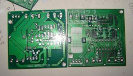
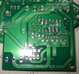
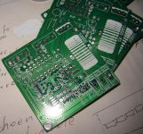
pcbs arrived
I've received my boards , they look great for me .
I´ll need time xD to build them.
regards!
ty ejtagle!
I've received my boards , they look great for me .
I´ll need time xD to build them.
regards!
ty ejtagle!
Attachments
Last edited:
I just had an interesitng idea, would it be possible to use this amplifier topology to create a free oscillating SMPS?
My idea is to use it in a full bridge configuration to crate the power rails for the actual apmplifier. Would the free oscillation frequency cause any RFI problems?
My goal is to design a compact scalable 100-500W PSU+amplifier to power bass speaker.
Any suggestions?
Its really off-topic, but yes, its possible. There are self-oscillating SMPS, they are mostly used at fluorescent lamps.
Skori Weblapja - Rezonns kapcsolzem tpegysg II.
Here is Skory's page, its in Hungarian, he is an expert in this topic, but im sure you will understand the schematics, and with google translator it will be better.
Do It Yourself!
For high voltage (more than 200 V): diode trick, or IGBT is needed.
Hello, as beginner please can you teach me what is diode trick ?
Hello, as beginner please can you teach me what is diode trick ?
Diode trick means bypassing the internal body diode. Using an other, better diode to conduct, or some other way to decrease losses. Check this tread:
http://www.diyaudio.com/forums/class-d/178317-body-diode-bypass-elegant-way.html
But if you are a beginner, DO NOT go over 200V. Better stay till 150V, start with low-power, or later use full-bridge (>1kW is possible with 150V FETs and full bridge). The problems exponentially increase over 200V.
Have a question,....
could this amp work stable with +/- 90V using IRFP4332 (IRFB 4332) or similar ?
is over and undervoltage protection important ? using torodial transformer power supply
If you pushing the limits so far, then an overvoltge protection should be necessary. At these high powers, bus pumping can easily push you over limit.
Since the IRFP4332 is a 250V it should handle +-90, but you would need a really good PCB layout for that. So as you said if you are a beginner, try with lower power first, better use full bridge.
(a 90V single-supply will do the same, with really cheap fets like IRF540Z, no bus pumping, so 90V for a 100V fet should be no problem).
does irf540n need a discharging circuit if driven in full bridge
SPafi quotes >100nC for IR2110 driver, since IRF540N is <71nC, it is not needed. For this small gate charges this will not enhance, since the driver needs some time to turn on its output transistors, so charging/discharging current to go up, and if you put an additional transstor it just adds delay.
In the datasheet it is said, what time is needed to get the 2A otuput, and its 25/17ns for IR2110. So the calculation
- without extra transistor (just diode): for 17nsec the average discharge current is 1A (linear rise is assumed), that means 17nC, another 54nC is supplied after 27ns, so total discharge time is 44ns (diode turn on is <4 ns so it is neglected)
- with extra transistor: the discharge current is first dictated by the resistor. I have no data for BC327, but 2n3906 is a simialr HF transistor, which says a turn on of >10ns. So for 17ns the discharge current is about 0,5A for average conditions (charge set 2x faster then discharge), that means 8,5nC. Then for 10nS the discharge current is 1A, that means 10nC. Total 18,5nC for 27nS, remaining 52,5nC charge is supplied with 3,5A (quessed current gain), takes 15ns. So total discharge time is 42ns.
The difference is totally in our calculations' and measurements' and datasheets' error tolerances, so no gain. This calcualtion is a quess, but it shows the way. Do the calculation for a FET with 150nC (our FET is good in every other property: low rdson, low Qcc, so we are not talking about old fets like IRFP260N, FORGET THEM). For that high charge it will shows the adventages of the extra transistor.
Laci!
The specified charge and discharge current is measured on short circuit. In the miller region it is only the half or less. This because the BJT may help also for lower gate charge somewhat. But I never tried it with low gate charge.
I don't know if it is needed (or beneficial) for IRF540N in this circuit, the builder has to try it!
Laci!
The specified charge and discharge current is measured on short circuit. In the miller region it is only the half or less. This because the BJT may help also for lower gate charge somewhat. But I never tried it with low gate charge.
I don't know if it is needed (or beneficial) for IRF540N in this circuit, the builder has to try it!
Even if it is half or less, the added BJT has turn on time, so with a BJT of infite current gain, but same turn on time the discharge is at least 27ns. So it may help, but not much. For high gate charge its necessary (its a really good idea), but for low gate charge: do the added complexity worth the improvement?
Does turn on time means no base current? I don't think so. Maybe VBE can go up to several volts, but for a very short time. Then it acts like a diode (+resistor).
While without BJT it's ~80...100 ns.
For me it doesn't, but not because of complexity, since the difference is only 2*1 pin.
so with a BJT of infite current gain, but same turn on time the discharge is at least 27ns.
While without BJT it's ~80...100 ns.
but for low gate charge: do the added complexity worth the improvement?
For me it doesn't, but not because of complexity, since the difference is only 2*1 pin.
btw guys i don't love using the old fets e.g irfp250 and 260 but i have no choice maybe to try 45v-0-45v full bridge using irf540 ,540n or irf640.
 out of topic a bit but just wondering in discreet circuit like the below can the gate discharge bjt transistor be added and will it be effective since i am using oldschool fets
out of topic a bit but just wondering in discreet circuit like the below can the gate discharge bjt transistor be added and will it be effective since i am using oldschool fetsAttachments
Hello
To operate the amplifier UCD With no load voltage of the MOSFET 90VDC IRFP4229 is recommended for the job?. Has an acceptable gate charge and switching time acceptable.
He had used the IRFP4232 But I've come to realize that they are too much for the IR2110. I made a mistake. Too lost in them (no-load heating amplifier)
Of the manufacturer International Rectifier There is not much selection of MOSFETs with a Vds voltage greater than 250V and efficient switching parameters. What do you think?
The tests I did with the amp with IRFP4232 were nothing unusual, in charge with +-85V @ 4Ohms power is very good, with acceptable audio quality (to ear).
Now I have to detail is the DC offset at the output. Involving a re-design of the PCB.
Greetings!
PS: I use a translator
- Home
- Amplifiers
- Class D
- UCD 25 watts to 1200 watts using 2 mosfets