This is smoke generator. Check reference voltages! Negative rail vs. GND!
1. Do you mean PIN 1 from IC4 NE555 ? have change from negative rail to GND in schematic look attachment otherwise I cant find the fault.
Can you assist me ?
2. DP2000-M-01.pdf Attachment schematic from professional digital amp with IR2113 IC, in this design we can see short circuit/overcurrent protection
I think here we can find some ideas to improve our UCD
Any comments about this design ?
Attachments
1. Do you mean PIN 1 from IC4 NE555 ? have change from negative rail to GND in schematic look attachment otherwise I cant find the fault.
Can you assist me ?
2. DP2000-M-01.pdf Attachment schematic from professional digital amp with IR2113 IC, in this design we can see short circuit/overcurrent protection
I think here we can find some ideas to improve our UCD
Any comments about this design ?
The DC protection is a crowbar protection, which should trigger the other protection (overcurrent), if not, then it can be used as an explosion-effect.
The schemtaic uses a shunt to sense current. Problem: you choose low Rdson fets, and low R inductors to increase efficiency, the shunt increases your resistance. Otherwise it is really easy, you can design it yourself, but all these design only sense ONE SIDE! (so the FETs should be designed to withstand short circuit for a short time, until the one side sense is triggered, trigger should be deisgned to be not to fast, but not to slow, if too fast, transients trigger it, if two slow, killed FETs).
1. Do you mean PIN 1 from IC4 NE555 ? have change from negative rail to GND in schematic look attachment otherwise I cant find the fault.
Still not good. Input of the protection circuit is at -85 V, but output is around 0 V! Who will carry the signal through? You need a level shifter (or different control point, like SD input).
 hi guys pls can you post a simple discreet schematic which can drive irfp260 or irfp250 with this circuit . i would be more than glad to use tc or maxim microchips or the required fets "irfb's or 4227's" but at my location i have to go through all the strugle to work with the available parts . pls guys a discreet schema to drive my fets with this circuit. i have used irf540 they are excellent compared to the above but i need to use high voltage be blessed all of you stewin
try irfp260 they are not the best to use but they are superior to the irfp240 i.e if you have no choice.and better use low voltage if you insist on t106-26 or mount it far from your pcb because at high voltage like +/-70 it generates heat equivalent to a standard soldering gun .or try 30turns on a gaped ETD core it will handle high voltage comfortably cheers
hi dzony988,u can try to get T106-2 core or T130-2 core
with t130-2+17x0,1mm wire parallel (home made litz) u can go up to 1500W RMS on 4 ohm with no heat!
hi ionutzxpo how much are they and which web site or manufactures can deliver to east africa if you order like 5 pieces . thanks 4 that info btw cores and class d mosfets and the tc4421 chip were my biggest set back
lucky for me ir2110 and 2153 are the ones availlable.Hi to all
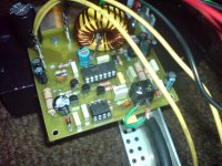
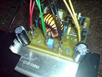
I finished amplifier. It works, sound is amazing, clear, powerfull bass and other. I add two capacitors 470uF near output fets, 4.7nF paralell with 100pF on imput stage. I was impatient to build this amplifier and i use IRFP240 for output stage (irfp260, 20 pieces are in other apartman)
No noise, transistors are cold, tip31c too, everythink is just fine but output coil is VERY VERY HOT,even on the small force. I dont know what can i do to fix this. In my contry I can't find etd cores or T130-2 or similar.
For output filter i use Iron Powder core T106-26 with 1mm gap and 24 turns of 1.2mm wire (20uH) and capacitor 1uF.
Any sugestion? Thanks a lot
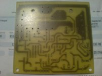
P.S I atached photos of my amp
I finished amplifier. It works, sound is amazing, clear, powerfull bass and other. I add two capacitors 470uF near output fets, 4.7nF paralell with 100pF on imput stage. I was impatient to build this amplifier and i use IRFP240 for output stage (irfp260, 20 pieces are in other apartman
)No noise, transistors are cold, tip31c too, everythink is just fine but output coil is VERY VERY HOT,even on the small force. I dont know what can i do to fix this. In my contry I can't find etd cores or T130-2 or similar.
For output filter i use Iron Powder core T106-26 with 1mm gap and 24 turns of 1.2mm wire (20uH) and capacitor 1uF.
Any sugestion? Thanks a lot
P.S I atached photos of my amp
Attachments
... everythink is just fine but output coil is VERY VERY HOT,even on the small force. I dont know what can i do to fix this. In my contry I can't find etd cores or T130-2 or similar.
...
Any sugestion? Thanks a lot
Use gapped ferrite core, and keep distance between gap and wire!
Why the core is heated at all? Is frequency to high and that core can not withstand?
The magnetic field introduces current flow into the core and generates heat.
They are called eddy currents.
I have found it good practice to use inductors with a higher current rating than normal.
- Home
- Amplifiers
- Class D
- UCD 25 watts to 1200 watts using 2 mosfets