I bought a Lepai LP-2020 to see if that really is as prone to break as it appears here, i already modified a laptop psu for it, lowered the voltage from 19V to 13V.
As for the prototype, its not the design thats basically wrong, i believe the heatsink isent flat so that part of the fets dident have proper contact with the heatsink.
Also the gate resistors were 22 ohms which i think is alittle high for 400+ kHz operation and the gate diodes were 1N4148 which dident have anywhwere near the current ratings needed for a fast discharge, so im not all that suprised it failed.
Before i left it to play music i did a destructive test, i hooked it to a 4.6 ohm dummyload and turned the bass all the way up on a mp3 player and turned the volume all the way up, this the amp survived and no clipping was observed.
The gate resistors will be lowered to 10 ohms and the gate diodes replaced with 1A UF160's, also the heatsink will be replaced with one that have a proper surface and i will also mount the board properly.
If this still causes it to blow up, well then i'll abandon the design and try something else when the MAX913's arrives.
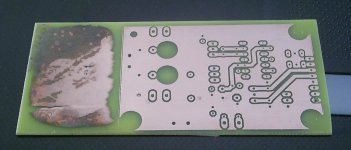
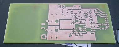
Ok. Changed a few components, and skipped the big capacitor in the input ...
Now it starts up every time, but only with a load (speaker or 8 ohm resistor).
Switching freq is 235 kHz
Because I had to remove the big cap ther is 0,6 V DC on the output .... need to find a solution ... any suggestions??
Also need ot find a way to make it start without the load ...
Otherwise it seems quite good for a breadboard circuit
And I think it is an improvement over the original ........
Hi Baldin,
Refer to your schematic ,is there any noise problem still?
Hi opor
There will always be noise when building up a class-d amp on a breadboard, with long leads hanging out everywhere") ...... but that will be dramatically reduced when you get it down on a good PCB .....
...... but that will be dramatically reduced when you get it down on a good PCB .....
And whether this circuit has more noise problems than others .... is a bit harder to tell before you get it to the PCB ... but I would think not
As I said I think it's an improvement over the original circuit.
I will not take it further myself, as I'm still improving on my own amp, (not UcD) .....
Best regards Baldin
There will always be noise when building up a class-d amp on a breadboard, with long leads hanging out everywhere
...... but that will be dramatically reduced when you get it down on a good PCB .....And whether this circuit has more noise problems than others .... is a bit harder to tell before you get it to the PCB ... but I would think not
As I said I think it's an improvement over the original circuit.
I will not take it further myself, as I'm still improving on my own amp, (not UcD) .....
Best regards Baldin
hi baldin,
off topic:
I want to make a class d amp with very low propagation delay, full bridge on single supply with all SMD parts. i have the thing running in LTspice but i want to be sure that i do not step over anybodies toes. Especially Crown since i want to make it to run without dead time because the SMD transistors will have to dissipate very low power, so i have to use something like the BCA method.
regards,
savu
I am wondering what is considered good RF suppression from a digital amplifier.
I designed a three channel class d running +- 42 volts. 4 layer board
It is mounted 3 inches from the (Mechanical ganged capacitor) tuner section in a Pioneer reciever because no other space was available. Eva appears to be very knowledgeable on D amps
The AM works fine up to 1200Khz (D amp frequency)
The FM has noise in stereo mode.
My oscilloscope is an old 10mhz model, but shows no ringing.
Off topoic:
I have a same kind of question about UCD. what is the patent lies on UCD..?? is it for as a whole concept? or the oscillation/self oscillation? or a specific design??
It is said 'universal class D'. which means any class D goes under that patent or what? if not can anybody give me a live example(a class D amp) that doesn't go under UCD patent?.. I'm so confused.. with these techniques and patents when learning and designing class D amps.
wish if Eva could answer for this but any helping post will be appreciated
Thanks in advance !
best regards,
Lycanlk
The patent is for a class-D amplifier based on a phase-shift oscillator using the output switching ripple voltage after the low-pass filter as the source of the switching signal.
There are other post-filter NFB topologies but none that I know of have the elegant simplicity of the UCD concept.
There are other post-filter NFB topologies but none that I know of have the elegant simplicity of the UCD concept.
I bought a Lepai LP-2020 to see if that really is as prone to break as it appears here, i already modified a laptop psu for it, lowered the voltage from 19V to 13V.
As for the prototype, its not the design thats basically wrong, i believe the heatsink isent flat so that part of the fets dident have proper contact with the heatsink.
I'm not sure if Lepai have fixed things with newer revisions of their TA2020 based amp, but I've found that you need need to remove a diode that is connected to the Fault Pin of the chip. This has saved my TA2020 from burning out.
As for the heatsink, I find the existing one is ok but I unsoldered mine, then drilled out the mounting holes for the heatsink on the PCB. This allows the existing PCB to sit flat.
It's a shame that this amp has a few little bugs but I've found that they are easy enough to fix.
I already have a few mod pland for this amp. Delete the diode and replace input lytics with little plastic caps, maybe replace the output inductors with two toroids with two windings on each.
Hi Tekko
can you offer latest schematic with important changes for UCD amp like turn on delay / fast off ?


- Home
- Amplifiers
- Class D
- UCD 25 watts to 1200 watts using 2 mosfets