Ok..i will recalculate the snubbers but now i am using 1nF and 4.7 ohm,should i decrease capacitance?(180 pf output capacitance for irf540z).
I am using your schematic for the amplifier section but with lm317/lm337 voltage regulators and local bypasing at buffer and comparator.
IMAGE
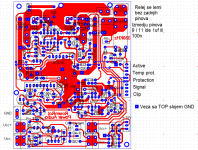
Current layout..not much modified since i got no real feedback(except 1 answer).
I wanted to avoid a long feedback wire that will act as an antenna/inductor(some designs on this forum even have it crossing the switching bus).I can not understand how that could be better since more switching noise will be injected in comparator input...
Jumper wires for protection section and long wires for comparator supply are not o concern in my opinion since i have lots of local bypasing and filtering resistors.

IRF540Z are good FETs, so they should be okay. What is the no load current uptake of the circuit?
Hm..i do not know what happend but now i can not measure the switching peaks anymore(i only changed probe position)..it looks like this with 5A load.

Current draw is:
neg supply: 40mA and 80mA when oscilating
pos supply: 30mA and 70mA when oscilating
200mA Ac(if using half wave rectification)
Current draw is:
neg supply: 40mA and 80mA when oscilating
pos supply: 30mA and 70mA when oscilating
200mA Ac(if using half wave rectification)
Last edited:
Hm..i do not know what happend but now i can not measure the switching peaks anymore(i only changed probe position)..it looks like this with 5A load.
An externally hosted image should be here but it was not working when we last tested it.
Current draw is:
neg supply: 40mA and 80mA when oscilating
pos supply: 30mA and 70mA when oscilating
200mA Ac(if using half wave rectification)
Then the ringing was only caused by inproper oscilloscpe probe placement. It is good, but at comparator input it is clearly seen, that transients come back. Even so decrease the capacitor of the RC snubber network, since it is too much.
So far I am not quite sure what causing the distortion.
There is a problem with my scope measurements of opamp input..there is high frequency noise picked even with shorted probe so i added a shielded cable to the probe and made more measurements that are better,it seems now that low level signal is not so dirty..so there are in fact no transients or very small at comparator input..
20 mhz Bandwidth limited scope
full bandwidth scope shorted input
full bandwidth scope
full bandwidth scope ,residual at 6.5A near clipping, 1khz input signal, lots of hearable distorsions
20 mhz Bandwidth limited scope
An externally hosted image should be here but it was not working when we last tested it.
full bandwidth scope shorted input
An externally hosted image should be here but it was not working when we last tested it.
full bandwidth scope
An externally hosted image should be here but it was not working when we last tested it.
full bandwidth scope ,residual at 6.5A near clipping, 1khz input signal, lots of hearable distorsions
An externally hosted image should be here but it was not working when we last tested it.
Last edited:
Update(2)..increasing snubing capacitance decreases distorsions alot..so i need a square wave as perfect as possible...
Try to make a measurement with accurately compensated probe. Then set snubber. Not to too high.
And then work on feedback design to minimise the transients going to the comparator input. It mainly involves changing PCB layout.

Update(3)
50 ohz hum is low enogh now with 2 0.47 capacitors instead of a one.Also hiss is lower now,i am using 10x gain and 4x low noise buffer with +-7 volts suplies.
Distorsions are more hearable in freqencies <100hz,can someone tell me why?Over increasing snubbers helps but i can not use the amplifer with 200-300mA quiescent current..
Last edited:
What do you think about this simple limiter that I create?
It use AN6884 vu metar, LDR07 photoresistor and +12V supplay.
Two leds in paralel. One (high lightnes) for LDR and one for front panel of chasis named on example "Limit".
With 10K trimpot on input of AN6884 we can adjust limit level.
Leds are on 5th position of VU meter for easy adjustment.
It use AN6884 vu metar, LDR07 photoresistor and +12V supplay.
Two leds in paralel. One (high lightnes) for LDR and one for front panel of chasis named on example "Limit".
With 10K trimpot on input of AN6884 we can adjust limit level.
Leds are on 5th position of VU meter for easy adjustment.
Attachments
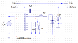
In previous post is schematic and conection diagram. Everything is very simple. And AN6884 conectors are in SIL conection (reactangle is first pin)
Here is schematic of AN6884. There is no need for datasheet because AN6884 is trivial vu meter like LM3914 and LM3915 but with only 5 leds
Trimpot on input is for adjust sensitivity
Here is schematic of AN6884. There is no need for datasheet because AN6884 is trivial vu meter like LM3914 and LM3915 but with only 5 leds
Trimpot on input is for adjust sensitivity
Attachments
 (in normal operation at 2A,4A and 8A rms into 4 ohm) using headphones.
With my new pcb (double side) noise is almost gone. I still have a noise but very small. I can only hear it when my ear is on twiter. One meter from speaker I cant hear enything. I dont know how but amp start to oscilate when I turn on power supplay every time. I didnt do enything about it.
-Res.freq. is 250KHz, output stage is with 20uH 1uF and IRFB4227 +-80V (2x2KW transformers)
-On aproximetly 250W 4ohms load I don have big distorsion (0.05%). On 1,5KW in full bridge 4 ohm load I didnt measure distorsion but for my ear is clear and good sounding, very powerfull
Honestly, I think that enyone can't hear distorsion with 1KW power with 2x18" subwoofers and 4x15" full range") )))
)))
That's why I dont care a lot for distorsion on big powers. For me more inportant is distorsion on low powers (20-150W) when I play music with frineds or home parties.
Heat is low, I adjust 45-50 deegres C temperature for start temp protection but even on full power in full bridge 4 ohms (2 ohms per chanel) temp protection never starts, bigger problem is distroyed 18" subwoofer Martin Wisman Ref18. I conect two of them in paralel in full bridge and one didnt survive. I think 1.5KW is to high for them)))))))
-Res.freq. is 250KHz, output stage is with 20uH 1uF and IRFB4227 +-80V (2x2KW transformers)
-On aproximetly 250W 4ohms load I don have big distorsion (0.05%). On 1,5KW in full bridge 4 ohm load I didnt measure distorsion but for my ear is clear and good sounding, very powerfull
Honestly, I think that enyone can't hear distorsion with 1KW power with 2x18" subwoofers and 4x15" full range
)))That's why I dont care a lot for distorsion on big powers. For me more inportant is distorsion on low powers (20-150W) when I play music with frineds or home parties.
Heat is low, I adjust 45-50 deegres C temperature for start temp protection but even on full power in full bridge 4 ohms (2 ohms per chanel) temp protection never starts, bigger problem is distroyed 18" subwoofer Martin Wisman Ref18. I conect two of them in paralel in full bridge and one didnt survive. I think 1.5KW is to high for them
)))))))I forgot to tel you. I have Volume pot 4.7K, then low noise buffer wit gain 2.5x then amplifier. Input cap to gnd is 4.7n and mids and highs are great.
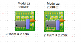
My new pcb has input "modules". single line 6 pin conector. One modul is for 250KHz (old schematic) and one is for 330Khz (Lacy's schematic). I dont have two differents PCB, when I test amp or something else, I only change "modul".
Above NE555 are two 9W resistors for current sens.
-Personaly I dont have osciloskope but I measure distorison with trivial metods, two amps, headphones, resitors, signal generator. And result of 0.05% at 250W and 0.11% at full power is information from my friend who measured amp for me on equipment for that
Attachments
- Home
- Amplifiers
- Class D
- UCD 25 watts to 1200 watts using 2 mosfets