Now I have to detail is the DC offset at the output. Involving a re-design of the PCB.
Is there DC at output from another DIYer with this Amp ?
If yes.....have a look at IRAUDAMP1 from IRF, there is in schematic to see how to solve it
my question to DIYer like Pafi, Lorylaci .... have build this amp....is it important to add DC offset adjust like in IRAUDAMP1 reference design ?
Hello all,
I`ve build 3 pcs of this amp, the 3rd pcs having dc at output, the other 2 pcs is normal no problem, i dont have enough time yet to check what exactly happen with the 3rd one, because it was ok after i`m finish it, and the problem come 3-4 days after, i do check little with ir2110 was ok, mosftet N ch both also ok, i think its maybe some parts not properly connected, for good reason is nothing blow, its just produce DC rails at output, and im currently using dc protect relay, thats why 1 ch of my amp not work after 3-4 days, maybe if anyone have problem like this one may share your solutions here, btw i`ll check it slowly because i`m little busy right now with my job.
regards,
Azmi
In the 2 amps I've done, I found DC to the output, even with supply voltages of +-50VDC. It shows when the amplifier on, the speakers "stand out" from its resting state. Does not affect sound quality, but it is uncomfortable.
Behind Several comments cited the use of a ServoDC on feedback to correct the imminent problem of design in the amplifier, even mentioned by the author of the Scheme (Maybe not in this forum, if not the forum where this amp came UCD).
Finally, the IRFP4229 recommend?
Greetings!
Behind Several comments cited the use of a ServoDC on feedback to correct the imminent problem of design in the amplifier, even mentioned by the author of the Scheme (Maybe not in this forum, if not the forum where this amp came UCD).
Finally, the IRFP4229 recommend?
Greetings!
Have a question....before will build this UCD
Have build DIY analog Mosfet Class AB amp (quasi Mosfet Amp from this forum)
Sound is really nice and balanced from the lows to the crystal highs..its a proven performer and hard to beat in terms of sonics and robustness
Whats DIYer experience in Sound about sound quality with this UCD Class D Amp ?
Does somebody have experience ?
have a look Attachment my UCD CLass D PCB
for + / -85 V DC
it has big GND ground plane on Top Side (Blue) DC detect, turn on delay, any claims or inprovement email me....
I want add at weekend overcurrent protection with Shunt resistor on positive rail like IRAUDAMP1, normally it should work
who is interested to share my PCB files for PCB supplier email me...
Attachments
Last edited:
nice one, NMOS before we go far with this amp, try to mount this amp together within one case, some have trouble having noise coming, i believe tacatomon have this problem too, i`ve visit forosdeelectronica.com forum, and most active person testing ucd there is him  . BTW NMOS ur pcb looks nice to me its double layer pcb? Now i`m trying to build class D no ucd and wanna see the different between class d ucd, i use this amp for sub atm.
regards.
Azmi
. BTW NMOS ur pcb looks nice to me its double layer pcb? Now i`m trying to build class D no ucd and wanna see the different between class d ucd, i use this amp for sub atm. regards.
Azmi
so, i`ll give class D no ucd is great, stereo in a case without noise, hiss or whatever, i`ll take some video later how hard and sonics this amp push. i`ve mount it with 30 0 30 vac 12 amp transformer,33k uf caps bank, mosfet is irf540N, i do simu with ltspice i`ve got it from another forums where this amp belong to, credit to the owner and of course im made some modification on it.
regards.
regards.
hi tacatomon
Well ... se ve bien tu diseño pero tu bobina es muy pequeña minimo 47 vueltas calibre 12 en un diametro de 1.5 pulgadas diametro ext y interior de 1 pulgada aprox 22uH mi solo se calienta un poco
ademas funciona excelente con irf640 a mas menos 50 vdc
The output power is given by the supply rails ... More or less something like sqrt (W * 2 * Rload) The maximum current is I = V / R and the maximum dissipation in the mosfets will PDmos = I * I * Rdson / 2 (Each mosfet works half the time! !).
With these calculations and we get an idea of how much power we can get. Actually the limit is given by the mosfets that we find in the market. 11.250 W are possible according to the author. It is "acceptable" one branch feeding +-300VCD. Would have to find those mosfets to withstand the voltage and current involved, about 38A RMS ... But most of you know that reaching those powers is absolutely deadly where you may be ...
The most with which I have tried is +-90VCD while empty. + In-charge are as 86VCD. I had some problems to start with this diet. At the start of testing this dangerous voltage, a branch of the amplifier up to 106VCD and the other was down to 82 ... As I said the creator of the amplifier, there are several causes for what happened to me.
1 .- Very low capacitance reservation. I used 8000uF.
2 .- the threshold voltage MOSFETs. He used the IRFP250
Perhaps I joined the two problems that caused the imbalance of voltage. Part of the explanation is that I was a part of the energy source is burned in the speaker, but some returned to the source through the topology of this amplifier. Being the limit voltage mosfets tend to act like diodes Zeners, limiting the voltage to 100V and making a branch is "Overload" voltage "return" ...
To start the amplifier ... Simple. After assembling, the coil assembly and verify the correct assembly of the amplifier (Armed with the power components for a 400W/4Ohms), proceeded with a power source with a symmetrical 50VCD 4A, a 100W lamp connected in series everything and put a small speaker to test the sound. At first made the pop classic, but it's a bit worrying, because sometimes you hear the sound as if it were shorted out and spend the entire DC to the speaker, but no, just a moment and gave me only the firsts. A bit of audio, well, a load of 4 ohms, well, that this output mosfets ... Warm, such coil, hot, burning to the touch .. Sound loud and clear. Not very noticeable switching noise. In the piezoelectric tweeters you will hear a slight hiss closer ear to these ... From there on out, is very quiet and you can do it with the appropriate cables and a good position of the coil.
For the latter, I used multilayer ceramic 330pF 100V
The photos, you already saw her ¬ ¬
Only there's more
Login to a private Photobucket.com album
Greetings!
Hi to all. I still have a problem with output filter because Serbia is on black list for most foreign companies and i cant order anything. Can anyone look at farnell and tell me order codes for several cores or inductors that can i use because one company from my country can order anything from farnell.
I saw on farnell few inductros in self case, also many ferrite toroide cores but i dont know can i use it.
Thanks and regards
Nikola
I saw on farnell few inductros in self case, also many ferrite toroide cores but i dont know can i use it.
Thanks and regards
Nikola
Hi to all. I still have a problem with output filter because Serbia is on black list for most foreign companies and i cant order anything. Can anyone look at farnell and tell me order codes for several cores or inductors that can i use because one company from my country can order anything from farnell.
I saw on farnell few inductros in self case, also many ferrite toroide cores but i dont know can i use it.
Thanks and regards
Nikola
I had terrible problems with hot inductors from Farnell.
These were power torroids and not class d torroids.
In the end I bought in a t106-2 powdered iron core and wound on 2 metres of 18SWG enamelled copper wire.
These worked very well and didnt even get warm.
You can buy the cores from www.amidon.com, I got the 18 SWG enamelled copper wire from local Maplin.
Last edited:
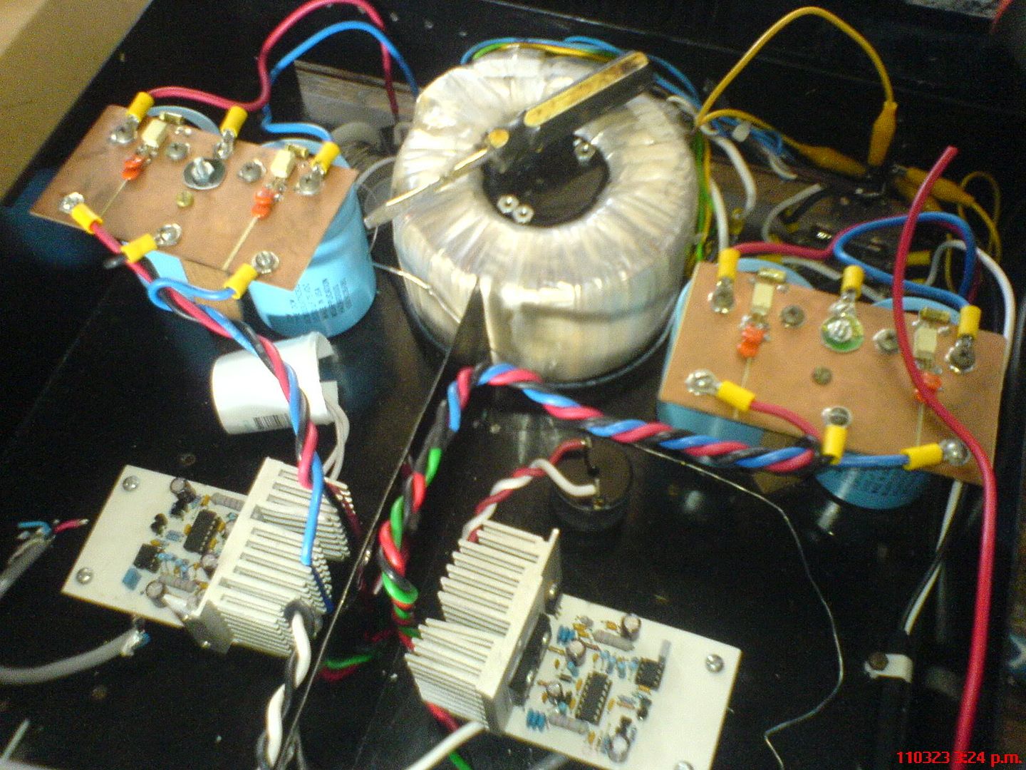
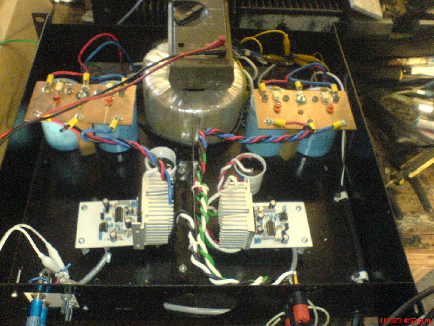
I've finally managed to put together a pair of UCD's in a single chassis. The problem came from the high-frequency noise to connect the 2 audio. The solution was as simple as "gimped " DC cables and output as seen in the photos. The output Mosfets are IRFP250N, the supply voltage is 55VDC. Now the noise is minimal with some output DC, some 650mVDC ...
The sound is GREAT! No different sounds to ear between Class AB.
Greetings!
Album.
The sound is GREAT! No different sounds to ear between Class AB.
Greetings!
Album.
hi taco..
you can remove lots of the dc on the output, you connect a 100uf capacitor in series with R7 to gnd, its the resistor from pin 2 to gnd... i have also 400-700mv dc on output now where is from zero to 10mv
Do you use 100uf electrolytic capacitor ?
thanks ugly,
no more DC on output.
It's a bit slow (136kHz), that's the next thing I'll try to improve.
change 330pf to 100 pf and you will get about 250 khz
I read several pages of this topic, and not come to the conclusion that I assemble it or not ...
Some say it works, others do not
is that I want to start a little sound to college parties .. you know .. no one will mind if it sounds good or not, just want it loud!, logical that this amp will be just for bass
I will use selected components, resistors of 1% metalfilm, much capacitance in the power system, short circuit protection and power-limiting and the inductor will be done in a custom company
Anyone betting that will work?
sorry for bad english .. I'm from Brazil, using google translator
Last edited:
Hi to all, can you halp me
I just noticed, whay that my amp dont have big power. And I found a mistake. When I play signal on example 1KHz, my amp have on output 40VAC before clip, the sine is perfect, everything is ok but that is without load on output.
When I connect load on output everything is ok but on big power my output has DC voltage above 4V and my dc protection turn off amp, that was I thinking that my amp dont have power beacuse protection turn off amplifier on 20VAC on output, that is 100W on 4 ohm load... My amp cant produce more power than 100W because protection and that DC, and I thought it was a bit 400W.
What is my problem? I think the output coil is bad because when I replaced the coil connections, the amplifier has not even include to turn on beacuse I have 6.2V on output, when I replaced the coil connections, DC on output was 0.12V.
My output coil is EE33 gaped Ferite core with 30 turns, its hot on big power and i dont know his inductance, that was an experiment with nuber of turns and core
Thank you, Nikola
- Home
- Amplifiers
- Class D
- UCD 25 watts to 1200 watts using 2 mosfets