An other method can be the sensing of saturation of the output core. If di/dt goes too high, then the core is saturated. It can be detected by a very small transformator, because only the switching freq. must be passed trough. In this state the stray field also increases with many chokes, so it may be detected by a simple coil near the output choke.
This method also works only as oscillation goes.
This method also works only as oscillation goes.
multisim is not that great simulator, I like LTspice for this kinda things
As you mught think, there can't be constant DC, cases like this are why for switching events I don't like multisim...or I don't have it set enough

If i see this schematic (real transformer model) all that remains in a simple case is Rp, Xm, Rs (the transformed shunt). The low freq content of current will be shorted by Xm, so the high freq content will be transformed only. But if I see the voltage on a series shunt, the high freq part os current doesn't change, so I have serious problems with multisim simulation. (but i only have multisim).
pafi:
An externally hosted image should be here but it was not working when we last tested it.
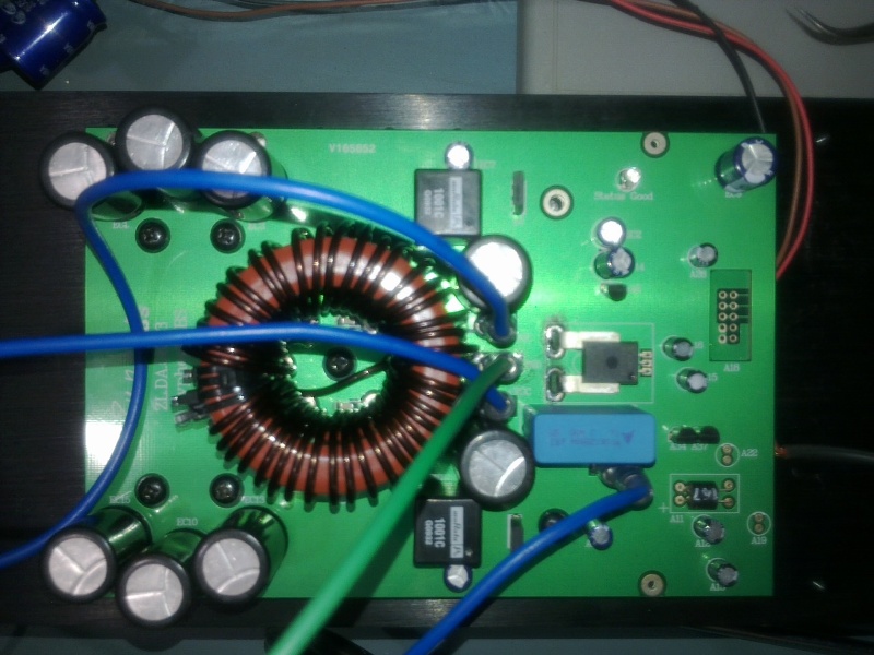
Here is how i plan putting current transformer.
Since I having problem with multisim simulations, the best method would be experimenting. I would not like to use series shunt (then why the heck i am using low RDSon FETs).
Using FETs RDSon as shung is one of the best, buts its really difficult to implement, unless its integrated into the driver (like IRS2092)
There are hall-effect based current sensors also. Allegro-micro.
Also a hall sensor can be put directly into the air-gap. Maybe this could work, but it needs special attention (shielding, filtering), because it is disturbed by electrostatic and magnetic interference.
Allegro Hall Effect Device used by me gave impressive results, but using output coil as current transformer was cheapest of all i tried successfully.
pafi:
Here is how i plan putting current transformer.
You mean pin 2 is starting, 4 is ending, and 3 is center tap? Theoretically it should work (as long as oscillation goes), but inserting inductance (only leakage, but still...) directly into drain is not a good thing. If you can keep it below 20 nH, then try it!
Using FETs RDSon as shung is one of the best, buts its really difficult to implement, unless its integrated into the driver (like IRS2092)
It's not that difficult, just needs some fine tuning. I implemented with 1 IRFU310, 3 resistors, 2 capacitors, 1 BC846. It's not precise, but worked very well. I have no any good reason why I haven't returned to this. I was simply lasy. (For 4 years? I'm stupid!)
Last edited:
...using output coil as current transformer was cheapest of all i tried successfully.
How do you use it as current transformer, and for what frequency down to?
How do you use it as current transformer, and for what frequency down to?
The CT was made 1:1 over output coil.[primary and secondary have same number of turns in my case it was 40 turns]
I limited the dutycycle to 10 to 90% in order to make sure i never run out of pulses while switching at 250khz and then averaged the output of CT using full bridge rectifier made from schottky and limiting was applied with optocoupler and SCR latch based on different time constants.
Last edited:
Workhorse: Using your method: otuput coil as current transformer would be the easiest method. But I cannot simulate it, and if i calculate it manually using the transformer model, it seems like not working.
Pafi: as my calculations a T37 with 1-1 turns would not saturate. (at 50A B=0,03T) This would mean 4nH (2mOhm impedance at 250 kHz, 16nH end-to-end), and this is shunted with the transformed secunder load (2 mOhm). This connection only needs one core, and it could even detect cross-conduction (it has double sensitivity for that).
Pafi: as my calculations a T37 with 1-1 turns would not saturate. (at 50A B=0,03T) This would mean 4nH (2mOhm impedance at 250 kHz, 16nH end-to-end), and this is shunted with the transformed secunder load (2 mOhm). This connection only needs one core, and it could even detect cross-conduction (it has double sensitivity for that).
Workhorse: Using your method: otuput coil as current transformer would be the easiest method. But I cannot simulate it, and if i calculate it manually using the transformer model, it seems like not working.
.
Give it a try in real.
The CT was made 1:1 over output coil.[primary and secondary have same number of turns in my case it was 40 turns]
I limited the dutycycle to 10 to 90% in order to make sure i never run out of pulses while switching at 250khz and then averaged the output of CT using full bridge rectifier made from schottky and limiting was applied with optocoupler and SCR latch based on different time constants.
I still don't understand. A normal current transformator have to be in series with the main reactance. In an amplifier the choke is the main reactance at fsw. How could it be in series with itself?
I tried to draw what you seem to said, but it can't be correct. On R1 the whole power supply voltage arises. Please tell me what did you really built!
Attachments
Pafi: as my calculations a T37 with 1-1 turns would not saturate. (at 50A B=0,03T) This would mean 4nH (2mOhm impedance at 250 kHz, 16nH end-to-end), and this is shunted with the transformed secunder load (2 mOhm). This connection only needs one core, and it could even detect cross-conduction (it has double sensitivity for that).
Thats correct, but there is also some leakage inductance depending on layout.
On R1 the whole power supply voltage arises. Please tell me what did you really built!
During normal mode the voltage is much less than power supply rail especially when the modulation is happening, only in case of short circuit it builds up more voltage and give you indication. One more thing there is capacitor + Resistor based HP in series with secondary in order to get the HF switching ripple measurement only and LF is not sensed that way.
Hi,
The method captured the output current D class stadium with the transformer can not guarantee that protects the output stage at 100%.
1:if short-cut occurred at output near clip , does not work.
2:High-frequency sound, with power, it becomes too sensitive (transformer resonates).
a good attempt is to use a simple micro EE soft iron, which is connected to the audio output. (with very low R-C on primary).
Regards
During normal mode the voltage is much less than power supply rail especially when the modulation is happening, only in case of short circuit it builds up more voltage and give you indication. One more thing there is capacitor + Resistor based HP in series with secondary in order to get the HF switching ripple measurement only and LF is not sensed that way.
How would this possible in this circuit?!? On the primer there is a square with Vdd amplitude! Why wouldn't it be on secunder?!? You've missed something very important!
How would this possible in this circuit?!? On the primer there is a square with Vdd amplitude! Why wouldn't it be on secunder?!? You've missed something very important!
Square is on secondary, no doubt but not with VDD amplitude when audio current is flowing through speaker or load.
Give a try in real and see what is missing.............

Maybe it's got something with non-linearity or other things we neglected in our transformer modell. But so far I have no clue how or why it would work.
But from your words, Workhorse, i guess that this cannot measure exact output current, just output short (but then how can we calcute its treshold).
http://www.diyaudio.com/forums/class-d/98691-d-amp-back-14.html#post1190506
Here is the link of the post from other thread. Luks pointed on this first, so maybe he has some idea about it.
This is not a real answer. You are trying to make us fools. No schematic, no working principle, you gave nothing. Why wouldn't it be Vdd? And how this could help in sensing current?
Oh Listen Pafi, No one is making you fool here, got that.
Better Try it yourself & don't show your frustration like this.
Leakage inductance in this case plays a vital role and this scheme works best in short circuit only not for linear monitoring of current. But the thing is that it works like a threshold detector. The voltage rises very quickly up to certain level >>VDD during applied short circuit which enables us to have an indicator for that condition.
Last edited:
Workhorse!
Sorry!
I don't have time to try this, especially since it is undefined. If leakage has a basic role, then you should define where exactly the secondary have to be wound. And the rest of the circuit is still missing. What could I try?
Short circuit? It doesn't mean current is flowing. Where is the threshold, and what defines it? Saturation? (What else could?) Then this must be based on the theory I've mentioned before, in #821, increased di/dt during saturation.
Anyhow, this is not a current transformer.
Workhorse!
Sorry!
I don't have time to try this, especially since it is undefined. If leakage has a basic role, then you should define where exactly the secondary have to be wound. And the rest of the circuit is still missing. What could I try?
Short circuit? It doesn't mean current is flowing. Where is the threshold, and what defines it? Saturation? (What else could?) Then this must be based on the theory I've mentioned before, in #821, increased di/dt during saturation.
Anyhow, this is not a current transformer.
If you don't have time to try this, its your wish.........
I can give you some pointers , wind the secondary on one side of inductor with thin wire but same number of turns to maintain same ratio, don't spread the winding. Yes the working is based on leakage inductance + saturation of core, no doubt on that.
- Home
- Amplifiers
- Class D
- UCD 25 watts to 1200 watts using 2 mosfets