Hello sir ! Is it working correctly this class D amplifyhave fun")
Bad design
basically it does not bring anything new alone, desires to sell your Pcb, and with its anti oscillation protection it just makes it too noisy ……… ..
Hi Stewin,
I have finished double feedback. Here my Schematic if you interested.
Basically this is standard IR based, but the key is use higher LPF cap 1uF instead of 680n or 470n to lower the ripple so that during start it will not take over switching oscillation (usually get 60-70kHz if oscillation failed).
Double feedback you need to be careful of fail start. It can damage your speaker. SO I add Fail Switching protection
This is firm design. PCB available in indonesia.
basically it does not bring anything new alone, desires to sell your Pcb, and with its anti oscillation protection it just makes it too noisy ……… ..
Hello everyone 
I like this simple UcD with IR2110 amplifier so i build it.
Everything it's fine, the amplifier was working from the first time i power it up. The offset was about 200-300mV and then i insert a 47uF capacitor in series with R7 (820R) So now the offset is 4-8mV at most.
The only problem with amplifier is that the self oscilating frequency is to low, about 120KHz. From what i read the self oscilationg frequency normally, at this schematic, is around 260KHz.
How can i increase this frecvency ?
I try to change C1 from 330pF to 100pF but no luck
Is it possible to increase this frecvency to about 400KHz just like original schematic made by Bruno himself ?
I use IRFP4220.
Any advice is highly appreciated !
Attachments
Can someone please send me the needed PDF files of irs3000 detex audio with 4 mosfets.
I want to try to make this class d amp and see how it performs for the first time.. My email is jlungumax@gmail.com . Thanks in advance
I want to try to make this class d amp and see how it performs for the first time.. My email is jlungumax@gmail.com . Thanks in advance
Hello all kartinos new amplifier
have fun all and kindly post your comments and ideas
https://m.facebook.com/groups/859707677375336/permalink/5113445042001557/
have fun all and kindly post your comments and ideas
https://m.facebook.com/groups/859707677375336/permalink/5113445042001557/
Attachments
i had a chat with kartino and told him i was sharing his amp for discussionIts a private group, schematic is not for whole public
please do not post here any links without permit from the group
nice design , looks promisingI am also busy with design, a other version who is not the same and still in front end condition.
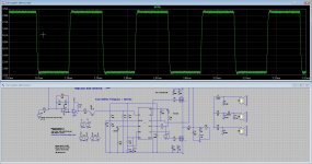
Give nice 10 khz square.
I am learning about class D I do not now it will sound well but it did pass through a triangle in very clean state.
Thanks, I go build a test version, as a front end. doe more on extra examen extra feedback.nice design , looks promising
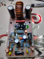
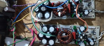
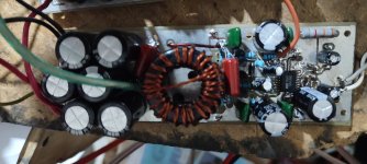
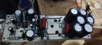
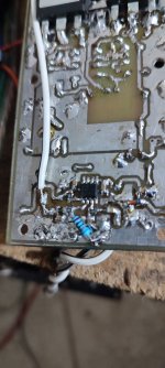
hi all , i have gone back to basis and made this amp in smd style . also i have added a buffer to assist drive the fets
The amp is working fine , the main issue is the hf hissing noise.
i prefer this amp rather than sigma delta because it is stable even with no load while woking.
kindly any opinion will be appreciated .
The amp is working fine , the main issue is the hf hissing noise.
i prefer this amp rather than sigma delta because it is stable even with no load while woking.
kindly any opinion will be appreciated .
Attachments
-
gtY ucd 2500 np top comps.pdf41 KB · Views: 154
-
gtY ucd 2500 np schematic .pdf31.4 KB · Views: 183
-
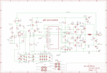 gtY ucd 2500 np schematic.png504.6 KB · Views: 277
 -
 IMG_20220902_181213.jpg287 KB · Views: 228
 -
 IMG_20220902_185412.jpg320.2 KB · Views: 137
 -
 IMG_20220902_185433.jpg278.9 KB · Views: 127
 -
 IMG_20220902_162848.jpg328.1 KB · Views: 135
 -
 IMG_20220902_162853.jpg309.7 KB · Views: 138
 -
 IMG_20220902_164318.jpg236 KB · Views: 133
 -
 IMG_20220902_181159.jpg264.7 KB · Views: 224
 -
gtY ucd 2500 np.zip114.5 KB · Views: 128
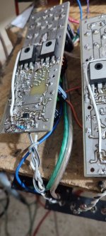
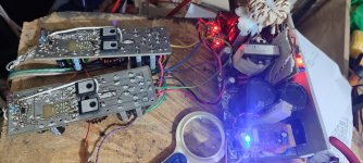
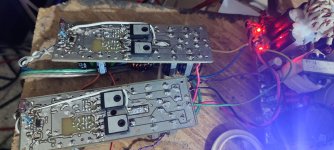
thanks bro for the reply, the amp is ucd ,Buffers were unnecessary. Remove it its inducing noise. And its is ucd. Its use single bit comparator i dont know if its delta sigma oscillator. But i think it is. But nice pcb
the reason i have included buffers is to assist the ir2110 ,. in the previous versions i used without buffer and the ir2110 used to heat alot
even though i had used 22ohms resistor gate drive.
also i wanted to drive multiple fets to be able to drive 1ohm to 0.8ohm load like car amplifiers . e.g taramps or many latest car amplifiers which use +/-70vlts to +/-160vlts fullbridge and supports up to 0.5ohms .
Last edited:
- Home
- Amplifiers
- Class D
- UCD 25 watts to 1200 watts using 2 mosfets