this waveform has some strange points
1. 0V points of input waveform,modulation waveform frequncy drop or stopping.
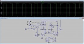
this circuit has phaseshift problem.without input voltage this amplifier not oscillate
and with small input voltage variation amplifier start and stop oscillation
An externally hosted image should be here but it was not working when we last tested it.
This rather seems slew rate limitation. Output voltage simply can't change fast enough, due to the filter. This is normal. According to this waveform this amp can be very good. And if distortion is really this low, then it definitely worth trying and testing throughly.
this waveform has some strange points
1. 0V points of input waveform,modulation waveform frequncy drop or stopping.
this circuit has phaseshift problem.without input voltage this amplifier not oscillate
and with small input voltage variation amplifier start and stop oscillation
Input is square from -V tp +V with rise and fall time of 1 uS.
Of course it does not oscillate when input is faster then amplifier response. It is the same witch classic UCD. This only happens when input "rise and fall" rimes are higher then sine of amplifier bandwidth
Phase shift at 20 khz is hmm 5-10 degree.
Last edited:
Input is square from -V tp +V with rise and fall time of 1 uS.
Of course it does not oscillate when input is faster then amplifier response. It is the same witch classic UCD. This only happens when input "rise and fall" rimes are higher then sine of amplifier bandwidth
Phase shift at 20 khz is hmm 5-10 degree.
I didnt test UCD with this type high frequncy+high amplitude
I guess that input filter capacitor cause phase shift,
you test it and no problem ,, its good

I used this circuit manage input signal of UCD/IRS900 type amplifiers
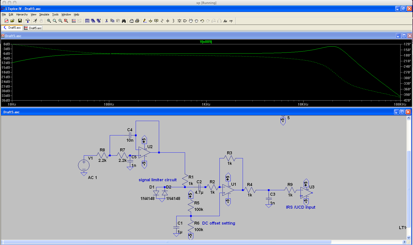
I used active highpass filter to reduse high frequncys
sometimes amplifier switching harmonics or SMPS switching I dont know what it is but it working perfectly
without this filter circuit eqalizer boost +12dB 16-20khz sound frequncy
UCD switching freqcuncy droped 300khz to 150khz and sound output very noisy
i think, your desing circuit is help to control that noice easily
thanks..
This rather seems slew rate limitation. Output voltage simply can't change fast enough, due to the filter. This is normal. According to this waveform this amp can be very good. And if distortion is really this low, then it definitely worth trying and testing throughly.
I agree and I just made some images to show:
First of all how to attach thumbs ?
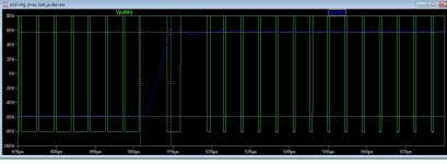
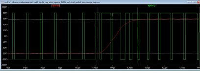
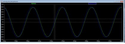
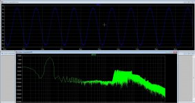
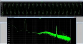
Output is set to all images +/- 60V, supply +/- 80V
Input square rise fall time was increased until output becomes more stable. Slower the V/us at the output slower rise fall time at the input (I mena input square rise fall time was adjusted to compare oring ucd to enhanced ucd)
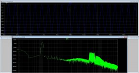
Input filter_enhnaced ucd is 1 k 2n2 low pass RC at the input of non inverting op amp
Original ucd without zobel network.
Enhanced ucd output filter paralel to 1uF main capacitor is RC zobel: 10 ohm 660 nF. Zobel pracitly make sifference only when output filter is not loaded. So when output filter is loaded with for example 1000 ohm this zobel makes it stil oscillated and it is kind of stable both for irignal and enchanced ucd
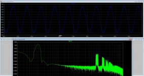
Orignal UCD_ 135kHz markers_ 14.5 V/ uS
Ucd Orig 117kHz markers, 13 V /uS
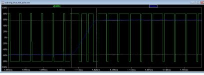
UCD orig, 11V/uS, this we can call minimum input rise fall that gives good output and stable
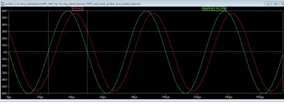
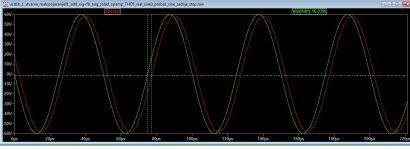
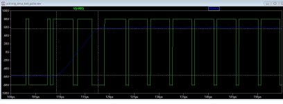
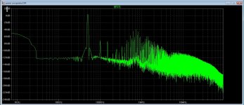
orig ucd_ This is phase delay at 20 khz 1.66 uS delay
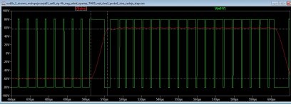
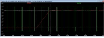
Enhanced UCD with input filter 13 V/uS 112 khz markers
Enhanced UCD with input filter, 9V/uS, 73 kHz, input rise fall time increased to get stable output
Enhanced UCD with input filter phase, 20 khz, 4.45 uS delay
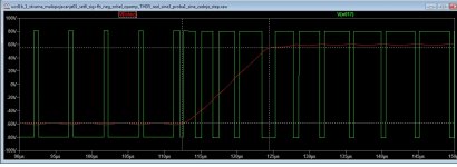
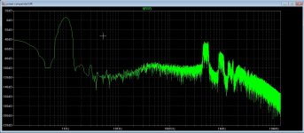
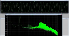
Unhanced UCD, no input filter, rise fall time input was adjusted to get stability, 12v/uS, this mean that it is only 1V/uS slower rise then original UCD !!! which is 13 uS
Enhanced UCD_ no input filter, rise fall at input adjusted to get stable output, 9.5 V/uS, compared to original UCD stable 11 V/uS
Enhanced UCD, no input filter 20 khz size phase delay, 2.39 uS
Attachments
-
 ucd_orig.jpg120.5 KB · Views: 1,194
 -
 ucd_thd_sa_filter_pase20khz.jpg126.9 KB · Views: 108
 -
 ucd_thd_orig.jpg142.8 KB · Views: 94
 -
 ucd_thd_ok.jpg121.8 KB · Views: 82
 -
 ucd_thd_bez_filtra_pase20khz.jpg132.7 KB · Views: 79
 -
 ucd_thd_bez_filtra_ok.jpg126.2 KB · Views: 81
 -
 ucd_thd_bez_filtra_granica.jpg118.5 KB · Views: 79
 -
 ucd_orig_phase_20khz.jpg118.7 KB · Views: 96
 -
 ucd_orig_ok.jpg120 KB · Views: 1,055
 -
 ucd_orig_granica.jpg100.6 KB · Views: 1,085
Last edited:
I just put this into spice http://www.diyaudio.com/forums/clas...cd-high-quality-power-amplifier-2x100w-4.html
(in page 1 is feedback network) and this seems SUPERIOR to all what I have seen so far !!. THD in my spice setup (the same setup) for all versions is 0,001 % compared to 0,1 % for original UCD, and compared to 0,01 % to this "enhanced ucd"
I have to check if here is thd frequency related.. But this circuit behaves differently then origianl UCD design.
Last edited:
all in all in this UCD+ THD is frequency dependent, 200 hz 0,0003%, 1000 Hz 0,002%, 19 khz 0,1% (more or less in spice), seems this integrator is "activ" in audio range, and at lower frequencies thd is lower.
I wonder what would be better in therms of "audio experience"?
I wonder what would be better in therms of "audio experience"?
all in all in this UCD+ THD is frequency dependent, 200 hz 0,0003%, 1000 Hz 0,002%, 19 khz 0,1% (more or less in spice), seems this integrator is "activ" in audio range, and at lower frequencies thd is lower.
This is a simple general rule.
I wonder what would be better in therms of "audio experience"?
Others do too, since the beginning of HiFi. And nobody knows the answer. (However everybody has his/her own opinion.)
Others do too, since the beginning of HiFi. And nobody knows the answer. (However everybody has his/her own opinion.)
LOL
But we have to admit, this UCD+ gives insanely good thd results !! If transient response is good, and if amplifier is stable this is "ultimately" the most linear amplifier. According to Russian forums this is actually NCORE.
I wonder why would this symmetry make any difference compared to "classic" "UCD+" this is kind of "differential design" hmm ?!
An externally hosted image should be here but it was not working when we last tested it.
LOL
But we have to admit, this UCD+ gives insanely good thd results !! If transient response is good, and if amplifier is stable this is "ultimately" the most linear amplifier. According to Russian forums this is actually NCORE.
I wonder why would this symmetry make any difference compared to "classic" "UCD+" this is kind of "differential design" hmm ?!
Differential, but this means only that all signals are twice as high in amplitude. All p signals are the exact inverted copy of the n signals. Therefore no benefit in THD. The benefit of symmetrical signalling is immunity for common mode disturbances.
The low distortion comes simply from very high loop gain and very low dead time. Exactly the same can be achieved in single ended topology. (If PSU rail is kept stable and clean.)
the most linear amplifier
You like ultimate statements. Maybe some day you will realize there are very few correct ultimate statements. And they are called laws (of physics, math, etc...) You remember, 1-2 weeks ago you thought loop gain cannot be increased. Now you've seen many different solutions. Don't limit the possibilities, unless there is a law against them!
Differential, but this means only that all signals are twice as high in amplitude. All p signals are the exact inverted copy of the n signals. Therefore no benefit in THD. The benefit of symmetrical signalling is immunity for common mode disturbances.
The low distortion comes simply from very high loop gain and very low dead time. Exactly the same can be achieved in single ended topology. (If PSU rail is kept stable and clean.)
You like ultimate statements. Maybe some day you will realize there are very few correct ultimate statements. And they are called laws (of physics, math, etc...) You remember, 1-2 weeks ago you thought loop gain cannot be increased. Now you've seen many different solutions. Don't limit the possibilities, unless there is a law against them!
What about using two identical D class amplifier designed in half bridge, i n"BTL" (bridge mode) would this help common mode disturbances, I know it helps for bus pumping etc...
I meant the most linear D class amplifier I (myself) put in my LTspice !!!
Of course I do not limit them. !! I thought Ncore was secret by Bruno P.
Well loop gain hardly can be increased if THD is kept constant in whole audio range, but here in ucd + design ,here at 20 khz thd equals classic UCD more or less, but WHO cares for thd at 20 khz,, when first harmonic of even 10 khz can not be heared.
This is all very nice in therms of "mathematics" and "lets make even better", but in real world I do not see if humans can hear the difference between 0,001 and 0,0001, also humans "it is claimed so, never tested mysef" can not hear thd below 1 %...
In spice I see some "weird behaviour of "ucd +" and before I decided what shall i make (and I plan to make something) I have to test all those impulse step etc responses, stabilities, no load stabilities etc in spice, like I did for "enhanced ucd".
Also all version both "enzhanced ucd", ucd+ and even smost simple UCD use op amps. At higher frequencies op amps thd by itself is not really that low (even for the most high end op amps),
I wonder how is op amp thd relation to the whole amplifier thd, if op amp is part of loop, for example integrator, etc. But clearly in spice I get higher thd using "real model" vis "ideal virtual model".
Probably if op amp is part of the loop "noise" produced by op amps (and non linearities) are reduced because of the nature of the loop itself which for example reduced thd generated by dead time , etc.
BUT first stage (audio only amplification) to desired level is not part of the loop.. etc
Last edited:
What about using two identical D class amplifier designed in half bridge, i n"BTL" (bridge mode) would this help common mode disturbances, I know it helps for bus pumping etc...
I meant the most linear D class amplifier I (myself) put in my LTspice !!!
Of course I do not limit them. !! I thought Ncore was secret by Bruno P.
Well loop gain hardly can be increased if THD is kept constant in whole audio range, but here in ucd + design ,here at 20 khz thd equals classic UCD more or less, but WHO cares for thd at 20 khz,, when first harmonic of even 10 khz can not be heared.
This is all very nice in therms of "mathematics" and "lets make even better", but in real world I do not see if humans can hear the difference between 0,001 and 0,0001, also humans "it is claimed so, never tested mysef" can not hear thd below 1 %...
In spice I see some "weird behaviour of "ucd +" and before I decided what shall i make (and I plan to make something) I have to test all those impulse step etc responses, stabilities, no load stabilities etc in spice, like I did for "enhanced ucd".
Also all version both "enzhanced ucd", ucd+ and even smost simple UCD use op amps. At higher frequencies op amps thd by itself is not really that low (even for the most high end op amps),
I wonder how is op amp thd relation to the whole amplifier thd, if op amp is part of loop, for example integrator, etc. But clearly in spice I get higher thd using "real model" vis "ideal virtual model".
Probably if op amp is part of the loop "noise" produced by op amps (and non linearities) are reduced because of the nature of the loop itself which for example reduced thd generated by dead time , etc.
BUT first stage (audio only amplification) to desired level is not part of the loop.. etc
~~~ % true
I'm do not talk about, commercial ,professional ,high end ,audio.
low frequncy UCD (fsw<300khz) affects THD 1% more than 5khz
like (hi-hat,cymbals,snare drum-set)
An externally hosted image should be here but it was not working when we last tested it.
for (doityouself) amplifier makers
250khz Fsw is ok for fullrage amplifier just try 200W 400W 1000w or more
make sure insert (Grizlek's desing) low pass filter to the input
low frequncy UCD (fsw<300khz) affects THD 1% more than 5khz
like (hi-hat,cymbals,snare drum-set)
Hmm, I think I do not understand this sentence, if you can explain.?
300 khz classic ucd give below 1% thd on whole range, 20 hz-20khz
I did sim this one, a discrete version of a comparator who I did found on internet and adjust some things, with that I have done some tests with it, and I get quite low distortion in ltspice, so maybe make a pcb and build that soon.
Only to test the ac sweep with a D class switching amp how I do that in ltspice, it is already slow with simulating when using switching.
I have test 1 Khz, 50 Khz, and mid and high power measurement, all give low distortions whith extra poles in system, cam made hysteric also but not done..
regards
Attachments
Hmm, but this is before filter feedback, we want filter to be part of feedback, so that filter is under control ?!
@Grizlek I am had a idea not to do that, because I do hybrids without feedback, so I kept coil out, ask myself to use a 24 dB bessel lowpass who is fase lineair and introduce not much distortion.
But is the filter such a part that will go out of control easely? or get I as a anti feedback guy the tube like sound character that way, this is why I did, but has also try including that with post forward on output for get right osc freq.
See mine stuf as a other way, I did post because I did get such low distortion, and was a little proud, I do not now much yet about this technologie, I do know afcouse about smps switch stuff, but this is new.
thanks for your respons.
Last edited:
@Grizlek I am had a idea not to do that, because I do hybrids without feedback, so I kept coil out, ask myself to use a 24 dB bessel lowpass who is fase lineair and introduce not much distortion.
But is the filter such a part that will go out of control easely? or get I as a anti feedback guy the tube like sound character that way, this is why I did, but has also try including that with post forward on output for get right osc freq.
See mine stuf as a other way, I did post because I did get such low distortion, and was a little proud, I do not now much yet about this technologie, I do know afcouse about smps switch stuff, but this is new.
thanks for your respons.
Post filter feedback with DTU paper (like you did) has problem that it can not oscillate at low frequency, but maybe using very high speed mosfet, comparators etc.. Even 100nS delay for dead time will make it oscillate quite high. 800 khz makes ferrite cores heat too much (and different materials should be used) etc.
Maybe lower higher thd is better then all this,.. but still schematics I linked (ncore version) has very low thd and oscillate at not that high frequency
Yes it can with some extra resistors and caps, I have also try bessel 24dB filter coils, these are fase liniair, but setting the low pass -3dB point on right place I can try what happens, nice hobby to try this kind of stuff.
see here on picture with different power settings, it is on 450 Khz, but get very low when drive hard as expected see last photo where almost clipped.
For people who not see protection, it is not on schematic but it is there, a one shot type.
For the core there are many different types, so maybe there is one who work, but with a 24dB bessel lowpass we can stay on 400 Khz.
Attachments
Last edited:
- Home
- Amplifiers
- Class D
- UCD 25 watts to 1200 watts using 2 mosfets