Maybe if you specified which amp you talk about you would have been answered. But don't expect any answer related specifically to your speaker and music listening habits. Nor about your shielding and grounding mistakes causing hum.
There are no really rugged amps here (except for ClassA ones). All amps in diyaudio are as is, no professional tests, no worst case consideration made, you can use them only for your own risk.
Some amps have some kind of protections, but I haven't see any that is unconditionally safe.
Using irs20957 with internal current protection on both mosfets, and external OVP UVP and speakr DC protection, probably adding even external relay DC protection will make this more or less pretty safe.
Grizlek,
I almost figured out what you wanted to ask about oscillation freqency and "feedback loop simulation" but neccessary details are still missing to get the answer.
You said no-load freq is 35 kHz. OK, but what is the freq with load? If it is 40 kHz, and the filter has a corner freq of 4 kHz, then no problem, this is a nice bass amplifier. But if normal oscillation freq is much higher, and no-load freq is near the filter corner freq, then it means that this is not a correctly designed or modelled amplifier. A good UcD amp doesn't change osc freq much depending on load. While designing you must assure fedback phase shift doesn't reach or approach 180 degree around the corner freq of LPF. If you share details, we can tell what to change to maintain this requirement.
If amp is oscillating near the corner freq then it is catastrophic.
Grizlek,
I almost figured out what you wanted to ask about oscillation freqency and "feedback loop simulation" but neccessary details are still missing to get the answer.
You said no-load freq is 35 kHz. OK, but what is the freq with load? If it is 40 kHz, and the filter has a corner freq of 4 kHz, then no problem, this is a nice bass amplifier. But if normal oscillation freq is much higher, and no-load freq is near the filter corner freq, then it means that this is not a correctly designed or modelled amplifier. A good UcD amp doesn't change osc freq much depending on load. While designing you must assure fedback phase shift doesn't reach or approach 180 degree around the corner freq of LPF. If you share details, we can tell what to change to maintain this requirement.
If amp is oscillating near the corner freq then it is catastrophic.
I will make drawigns.
I purposely designed that near LC corner frequency I am very near 180 degree, in such way I got higher "loop" supression and switching freqnecy, spice simulation showed at least 5 times lower thd.
Only problem is that I must not have load above for example 300 ohm. Then this very close area (40 khz) where phase is 179 degree will cross 180 degree and it will oscillate at 40 khz.
, this all works fine and oscillation frequency is stable, if our load is not too high,
This may be "repaired" with zobel using 10 ohm and 330 nF , but did not implement that.
when I connect classic 8 ohm speaker scope never shows any drop of oscillation frequency, only when I complete remove the speaker.
I also tested with audio precision for thd. works fine and stable.
Whole network is passive no additional op amp for amplification of (error + audio signal) to comparator.
BUT, I wonder (and I spent many hours of simulations) is it possible using op amps to srupress "loop" gain (plase do not catch to my English phrases) at switching frequency even more compared to loop at audio frequency. But phase is always affected and by reducing gain at switching frequency we reduce switching frequency.
I wonder what Bruno Putzeys did to achieve such loop that he claims 0,0001 % thd.
Last edited:
Using irs20957 with internal current protection on both mosfets, and external OVP UVP and speakr DC protection, probably adding even external relay DC protection will make this more or less pretty safe.
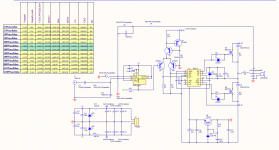
this one...
Attachments
Using irs20957 with internal current protection on both mosfets, and external OVP UVP and speakr DC protection, probably adding even external relay DC protection will make this more or less pretty safe.
Yes, with a correct PCB layout and relay with 100 V 30A DC disruption capability. Quite hard to find one with affordable price.
And safe (doesn't destroy the speaker or anything else) is different from robust (meaning works correctly whatever happens).
Yes, with a correct PCB layout and relay with 100 V 30A DC disruption capability. Quite hard to find one with affordable price.
And safe (doesn't destroy the speaker or anything else) is different from robust (meaning works correctly whatever happens).
I mean to say is this a robust design?like stable without oscillating or burning out speaker protection can be connected though to make it safe.
I purposely designed that near LC corner frequency I am very near 180 degree, in such way I got higher "loop" supression and switching freqnecy, spice simulation showed at least 5 times lower thd.
Only problem is that I must not have load above for example 300 ohm. Then this very close area (40 khz) where phase is 179 degree will cross 180 degree and it will oscillate at 40 khz.
Or at least this is the only problem you noticed. Lets stay with this! You have a problem with high quality factor of the LC filter. The solution is easy:
1: model L correctly, with realistic ESR! (For correct simulated result.)
2: insert an RC network parallel with C! (For real life stability.)
, this all works fine and oscillation frequency is stable, if our load is not too high,
This may be "repaired" with zobel using 10 ohm and 330 nF , but did not implement that.
You should IMHO.
when I connect classic 8 ohm speaker scope never shows any drop of oscillation frequency, only when I complete remove the speaker.
What about with near rail drive? What about speaker with discrete series inductance (as low pass filter)? What about piezo tweeter?
I also tested with audio precision for thd. works fine and stable.
With artifical load I guess.
Whole network is passive no additional op amp for amplification of (error + audio signal) to comparator.
BUT, I wonder (and I spent many hours of simulations) is it possible using op amps to srupress "loop" gain (plase do not catch to my English phrases) at switching frequency even more compared to loop at audio frequency. But phase is always affected and by reducing gain at switching frequency we reduce switching frequency.
If you can't compress gain at fsw, then try to increase it in audio band! Yes, there is a limit for this especially in basic UcD topology, but this is already one of the highest limit among topologies.
You can use different terminology, but it's your benefit if you notice that loop gain at fsw is exactly 1 in any stable oscillator.
this one...
If you don't want too much power (1200W is too much), and you draw a good layout, and you use proper parts, and you never short the output, etc... then probably it will not fry your speaker. With some luck.
However it has a quite high DC offset. Risky.
Speaker protection is for the mental piece. Usually it works always but not when really needed.
Yes, with a correct PCB layout and relay with 100 V 30A DC disruption capability. Quite hard to find one with affordable price.
And safe (doesn't destroy the speaker or anything else) is different from robust (meaning works correctly whatever happens).
but irs20957 contains DC protection using some bjt-s and sd pin (refer to refernce designs) no external relays necessary.
If mosfet rail is not damaged, and if OCP works, then it is more or less safe design.
Or at least this is the only problem you noticed. Lets stay with this! You have a problem with high quality factor of the LC filter. The solution is easy:
1: model L correctly, with realistic ESR! (For correct simulated result.)
2: insert an RC network parallel with C! (For real life stability.)
With RC network paralel to C spice simulation is stable even with 1 k ohm load. So there will be 1 k resistor paralel with load.
Impedance can only be lower then 1k, so no matter what load paralell to 1 k (RLC) it should be stable.
Yes, test was done on R.
Increasing gain at audio band increases gain at Fsw. so we need to drop at at f sw without affecting phase which can not be done.
What would be more advanced UCD topologies ?
but irs20957 contains DC protection using some bjt-s and sd pin (refer to refernce designs) no external relays necessary.
They wrote:
If this abnormal condition is caused by a MOSFET failure because one of the high-side or low-side MOSFETs short circuited and remained in the on state, the power supply needs to be cut off in order to protect the speakers.
So it also require controlling PSU voltage to make it safe.
If mosfet rail is not damaged, and if OCP works, then it is more or less safe design.
And if IR has solved the problem of stucking high-side drivers in this design. Or if DC detection and power supply cutoff is fast enough.
Quite many conditions... So OK, more or less safe. Go for it!
With RC network paralel to C spice simulation is stable even with 1 k ohm load. So there will be 1 k resistor paralel with load.
Do you mean AC simulation as before, or transient simulation with near-rail drive?
Impedance can only be lower then 1k, so no matter what load paralell to 1 k (RLC) it should be stable.
Even if it was a capacitive load (piezo)?
Increasing gain at audio band increases gain at Fsw.
Not neccessarily.
What would be more advanced UCD topologies ?
The most obvious is addition of integrator(s). Ncore is a less-trivial example.
But ask Chocoholic, he has (had?) a public project with really advanced control based on UcD. And in some of the topics here there was an other very high loop-gain design with multiple feedbacks linked and simulated.
They wrote:
So it also require controlling PSU voltage to make it safe.
And if IR has solved the problem of stucking high-side drivers in this design. Or if DC detection and power supply cutoff is fast enough.
.
If this abnormal condition is caused by a MOSFET failure because one of the high-side or low-side MOSFETs short circuited and remained in the on state, the power supply needs to be cut off in order to protect the speakers.
Why would there be mosfet short circuit in the first place if there is OCP ?
Why using power supply control, better then to use speaker relay control.
Also speaker resistance is 6-8 ohm , that 10- 15 A DC relay , not more at 80 V.
Who sells 100% safe amplifiers? So many protection implemented in original irf design reduce the probability of failure of speakers very much.
And if IR has solved the problem of stucking high-side drivers in this design. Or if DC detection and power supply cutoff is fast enough.
What problem ? why would high side mosfet stuck ? I have this working 5 years irs 20957 , hmm, maybe irs20955 has problems ?
Do you mean AC simulation as before, or transient simulation with near-rail drive?
Transient I just made. AC simulations shows that zobel does not help, but in transient it really helps. Also, how can we be sure that in real design it will behave like transient simulation.
Even if it was a capacitive load (piezo)?
Using 400-1200 W class D to drive piezo speaker alone ?
The most obvious is addition of integrator(s). Ncore is a less-trivial example.
But ask Chocoholic, he has (had?) a public project with really advanced control based on UcD. And in some of the topics here there was an other very high loop-gain design with multiple feedbacks linked and simulated.
Is this available on this forum anywhere?
https://www.hobbielektronika.hu/forum/getfile.php?id=253790
Pafi, please take a look at this link.
I tried simulating 2-nd order THD shaper, and it all works fine in AC analysis, problem with time domain is that with real op amps models, etc it will never work, too low PWM voltage level at the imput of comparator -80dB difference, compared to audio band frequency level.
I wonder if there is any need or possibility to achieve lower THDs.
If loop gain at switching frequency is so low, then it is very easily affected by many things (like DC components, offsets, etc), for example maximum of 5Vpp at audio band and 80dB gain difference, will produce only 5 uV of level at switching range.
Maybe this model can only work with 100% virtual models. I do not see how to work with comparator at so low levels.
Do you have any idea how can we improve THD, at real design.
I wonder if there is possible to make "first order THD shaper", problem with second order is that voltage levels are VERY LOW (too big loop gain difference at audio band compared to f swithcing). Problem with first order is phase. With second order we can use inverting configuration and phase shift is from + 270 to - 180.
With first order we have to use non inverting then, -180 is at too low frequency, if we use inverting - 180 is at 1Mhz or above.
Last edited:
I started spice experimenting, both AC and transient analysis, and I managed to get this working and got about 57 dB loop between fsw vs audio range.
Phase is crossed first time ad 45 khz and second time at 500 khz
If phase is crossed at about 150 and 500 khz, then at amplitude of input signal which reduces pwm to 150 khz, amplifier starts to oscillate at 150 khz.
In this case it does not oscillate at 45 khz.
all is based on DTU file
https://www.hobbielektronika.hu/foru....php?id=253790
Thd is reduced about 5 times.
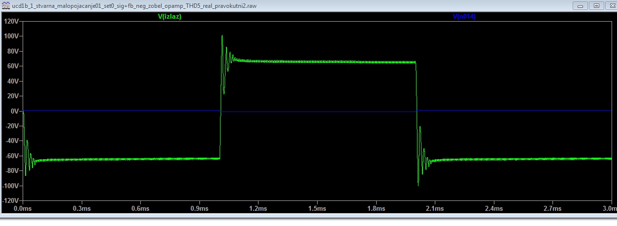
But, all nice in spice, but even in spice transient analysis, all those options where 180 degree phase is crossed, and where THD is reduced 10 times compared to the original UCD (basic), works fine until we do not put square signal at the imput. Rise time of square signal has to be slow , if rise the is anywhere near frequency of the first 180 degree crossing (about 40 khz) it will oscillate at 40 khz for some time.
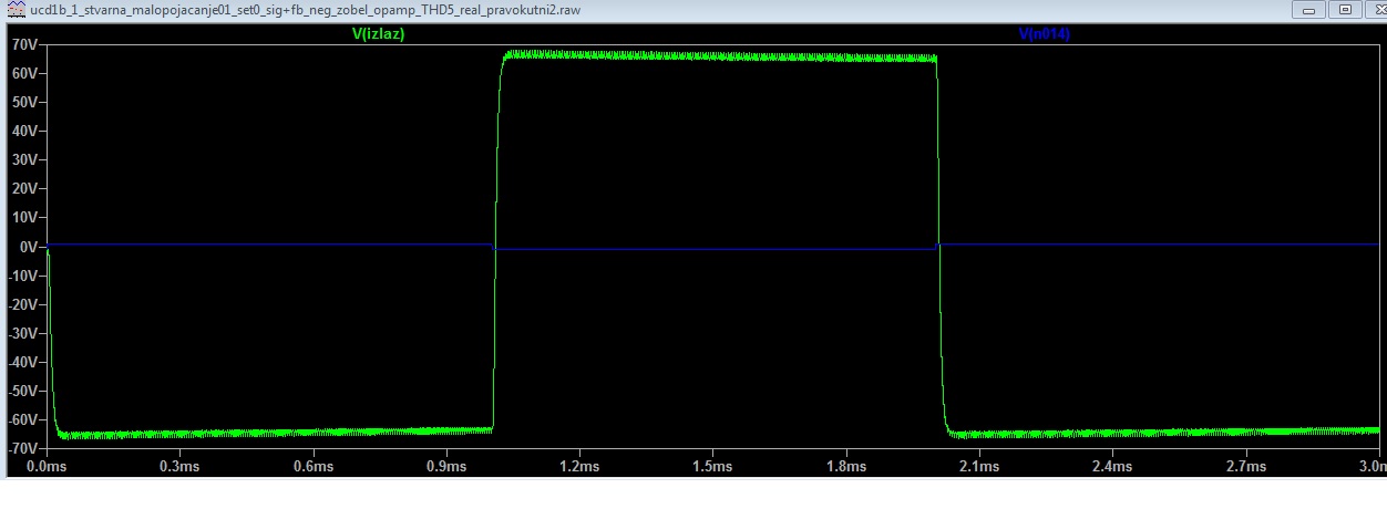
Another option is to put at the imput of amplifier RC filter that blocks all above audio range 30 khz, question is, should amplifier really have fast transinets to make "bass" membrane as fast as possible hmm. Is that really necesarry ?
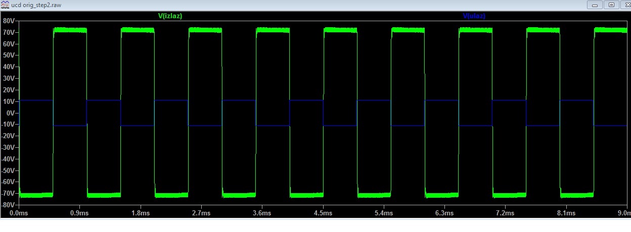
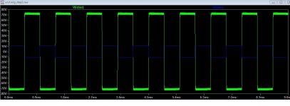
Classic UCD transient step 1us rise time, completely stable even without zobel netwrok :
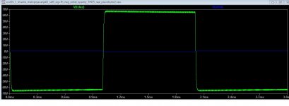
Enhanced ucd, step 1us tise time:
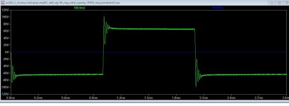
Enhanced ucd, step , but at the imput is RC filter at about 30 khz
So I wonder, for good amplifier, is step response, whose slope (rise and fall time) is faster then slope of sine of 20 khz, REALLY neccesarry.
Another option is to put at the imput of amplifier RC filter that blocks all above audio range 30 khz, question is, should amplifier really have fast transinets to make "bass" membrane as fast as possible hmm. Is that really necesarry ?
Classic UCD transient step 1us rise time, completely stable even without zobel netwrok :
Enhanced ucd, step 1us tise time:
Enhanced ucd, step , but at the imput is RC filter at about 30 khz
So I wonder, for good amplifier, is step response, whose slope (rise and fall time) is faster then slope of sine of 20 khz, REALLY neccesarry.
Attachments
Last edited:
If you can choose, what would you choose:
1) Classic UCD with about 0,1 % THD
This type of amplifier is very stable, and slew rate of output when input is square is very fast. According to my spice simulations, if we put step at the input of rise and fall time 1- 2uS (equals of sine at about 100 khz or above).
2) Enhanced UCD, adding extra poles and zeroes to the feedback:
We can reduce THD from 0,1 & to 0,004% (I managed to do this using this document above, in spice transient analysis), but now new problems arise, like mentioned in the previous post:
This can be repaired using RC filter and the input at about 25 khz.
In general which amplifier is better:
0,1% thd and bandwidth of 100 khz, compared to 0,001% thd amp with bandwidth of 25 khz ?
This is which I mentioned, but I don't have time for full analysis and even less to investigate the meaning and background of your statements and questions below.
very impressive grizlek. how about noise issues when mounting multiple channel in one casing ?? please post schematic of low distortion set up .
"low distortion setup" is just spice model, similar to link above (from hobby elektronika), and it is not step response stable. It can be stable if like I said input signal (at the imput of amlifier) is filtered low pass at about 25 khz.
This is never made in "reality". So I do not know how is it noise affected.
Maybe spice simulation does not show real reality behavior.
Also there are output DC component issues , opamps have to be input off-seted to zero.
In general, I think noise issues will occur when comparator input voltage levels are very low: Make "original UCD" with low amplification for example 8 times. Last time I made first 25 times voltage amplfication ucd, and there was much audible noise, when reduced amplification there was no audible noise. Also like Pafi said when audio signal s added with feedback signal it can be amplified using op amp so comparator gets higher voltage level.
Pafi, forget please all my questions except this one (all others who read please answer this general question) :
What would you choose:
1) D class amp 0,1 % thd (classic UCD) very stable to step response without any zobel network, and with at least 100 khz of "bandwidth". Accordingly slew rate is VERY VERY fast. Input step , makes output step VERY VERY fast. This is just classic UCD made here many times by many people.
2) D class enhanced thd to 0,004 %, but input audio signal has to be low pass cut at 25khz due to stability issues. (images above, step response).
This is more or less general audio "philosophical question" , DO WE NEED AUDIO amplifiers with bandwidth above 20 khz ???!!! Please explain.
Last edited:
Well I managed to get the "best" of two ways in spice, bandwidth vs thd: Input rc filter is now only 1k vs 2n2. And step input, output seems pretty stable.
Thd with 100nS dead time is 0,006-0,01% with Uout: peak = Vcc /2 : U out peak is 40V, Vcc is 80V.
Freq osc is about 520 khz
The same parameters for dead time and output voltage and ,very similar osc frequency (500 khz) for classic ucd, thd is about 0,1 %.
See attachment, better step response, input filter 3k /2n2.
Attachments
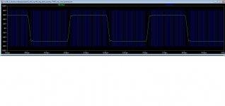
Well I managed to get the "best" of two ways in spice, bandwidth vs thd: Input rc filter is now only 1k vs 2n2. And step input, output seems pretty stable.
Thd with 100nS dead time is 0,006-0,01% with Uout: peak = Vcc /2 : U out peak is 40V, Vcc is 80V.
Freq osc is about 520 khz
The same parameters for dead time and output voltage and ,very similar osc frequency (500 khz) for classic ucd, thd is about 0,1 %.
See attachment, better step response, input filter 3k /2n2.
this waveform has some strange points
1. 0V points of input waveform,modulation waveform frequncy drop or stopping.
this circuit has phaseshift problem.without input voltage this amplifier not oscillate
and with small input voltage variation amplifier start and stop oscillation

- Home
- Amplifiers
- Class D
- UCD 25 watts to 1200 watts using 2 mosfets