I believe that there is a mistake in Q4 of this scheme because I think that the base should not be linked to the gnd, someone can give a help because it is not able to make it work ..
An externally hosted image should be here but it was not working when we last tested it.
It's a badly "designed" schematic generally. (Not designed actually, only put together different parts without real understanding.) I agree, Q4 base should be better used as input, and low end of the feedback network should be grounded instead of using it as input. But this problem alone is not likely to cause inoperability.
Q4 base should be better used as input, and low end of the feedback network should be grounded
Don't agree , the noninverting type of feedback is prefered . It has only one minus - low input resistance. [emoji12]
By the way , the UcD is more unstable vs the prefilter feedback amps. They need carefully adjusted feedback .The amps based on IR2092 configuration have no such issues in ALL conditions !!!
Yes, I think you like that "NOT" jokes.
I will not hijack this tread but has did some experiments with differend kind of d amps, delta sigma, pwm etc.
I was a little busy with a power comparator and some ideas for a highly liniair switching amp, however it do when feedback from speaker side of coil oscillate very low, and when on switching side it go to 1.8 Mhz, a proof also that the power comparator is quite fast.
I now the amp will oscillate when frequenty is 180 degree.
For me it is new, and never to late to learn.
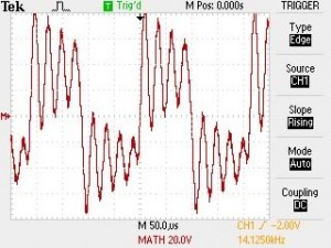
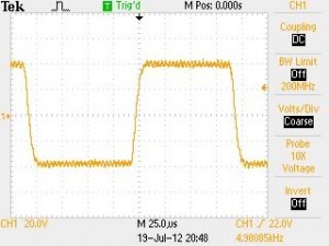
I think that you must have a personal opinion , and not post weird pictures .[emoji57]Dimonis,
Do you find this
more stable than this?
PS For the last year I made about 200 amps , 100-1200W , and not one had such issue [emoji38] .
www.powersmps.ru welcome !
Yes, I have an opinion, as you already wrote about it. But no, you can't refuse my right to post measurement results. If you think they are weird that means only that you never done such comparison. What is a pity, since this is exactly the question we are talking about.
Building 200 amps? I understand, you are too busy to make unloaded step response measurements.
Also too busy to answer some yes-or-no questions, to compose understandable statements, to learn the difference between inverting and noninverting feedback, to state why you prefer asymmetry and high offset drift and low input impedance and source impedance dependancy, to learn how UcD works, how LC filters work, to make quality evaluation, etc...
Hello Protech!
I quess you want to get more power from an SMPS for short time than it is designed for continuously. But this is not called oversizing. Dynamic power capability can be increased basically 2 ways: you can use primary buffer energy through the power converter, or secondary buffer energy directly. The first method requires a proper current limiting method that is made time-dependant, and the power stage must be capable of providing this current for short time (transformer must not saturate, etc...). The second method requires an output load characteristics with droop over a certain current.
If you need a specific advice you must show your schematic, and tell what happens exactly when you overload it, and what do you expect from the modification. But not all SMPS can be modified for higher pulse power.
"More heat" indicates something is probably not working correctly.
My favourite PSU topology is LLC with diode current limiter. Usually I use freq. modulation to make stable output, but this is not easy to tune correctly, so I suggest to use fixed freq. This topology works well with increased output capacitance, and every dissipating parts can be undersized according to average power, while higher peak power can be achieved. The long term power limit can be set by a (or 2) multifuse(s) on secondary side.
A correct PWM modulated half bridge or 2 transistor forward converter are also capable for such dynamic boosting, but they are not as efficient and EMI friendly.
happy new years mr pafi. sorry half bridge. smps based ir2153 big transformer 3kw in excellentit .660uf 459v and output 2000uf *2
Happy new year!
Have you read my posts?
Do you know what leakage inductance is and how to measure it?
Guys
I have designed fullbridge up to 4000W amp
Check my youtube channel. This is one of my UcD amp.
https://youtu.be/8C8vq2tPrLI
Above design to be honest not yet tested but all my design are working. If it is not oscillate, maybe you took wrong inverting in the low high gate. The feedback is fine. As it it half bridge no matter to invert or not.
It's a badly "designed" schematic generally. (Not designed actually, only put together different parts without real understanding.) I agree, Q4 base should be better used as input, and low end of the feedback network should be grounded instead of using it as input. But this problem alone is not likely to cause inoperability.
Hmmmmm....
Do you say that is from my schematics?
Please confirm.
Do you say that is from my schematics?
Please confirm.
No, these are waveforms of a pre-filter fed back amp and an UcD. But every classD amp without post-filter feedback has this kind of no-load step response, this is the intrinsic feature of an LC filter. Ringing can be damped at the expense of power loss.
Your schematic has other issues over this.
No, these are waveforms of a pre-filter fed back amp and an UcD. But every classD amp without post-filter feedback has this kind of no-load step response, this is the intrinsic feature of an LC filter. Ringing can be damped at the expense of power loss.
Your schematic has other issues over this.
Ok then.
UcD will need very good individual switching speed for the active parts. But non UcD can be less quality. For example D900 standard you cannot get it right with UcD topology. Max switching speed only upto less than 100kHz. But with non UcD, D900 can get 300kHz or more speed.
For UcD only discrete can go. That is why Mr. Bruno go for discrete. Now, no more secret

I have built many discrete UcD for Pro Audio. With supply up to 125Vdc.
I still believe that above failed trial is caused by the low and high side gate is inverted so then self oscillating is fail.
Here I attach ltspice file for above discussed schematic.
In the first page I schematic I found that is not correct way to merge LTP with current mode of course with IR2110 with voltage input mode. Then I create my schematic.
Regards,
Kartino
Attachments
Last edited:
Kartino-. It is possible to talk to you privately, as I would like to buy a complete project, just tell me the value in US Dollars.And Pafi, you said the schematic has other issues. then please tell.
- Home
- Amplifiers
- Class D
- UCD 25 watts to 1200 watts using 2 mosfets