hi all,
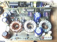
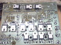
i face some problem . When this amp is in idle, two mosfets is getting warm ander few minute i feel that it is hot. Is something wrong? It should not be.
This is my schematic.
tip31c
Im gonna try a small modification on this circuit, tie pin 1 on LM311 to ground and use pin 7 as output instead, according to the datasheet, the LM311 would have much shorter rise and fall time with pin 7 as output.
Heres a schematic of what im gonna try:

Great. Your common sense is improving. If you reduce the voltage swing required on collector output too, it will be even faster. In the attached picture, pin 7 only has to move a bit more than 2 diode drops up and down (assuming that pin 7 in its low state will be typically half a diode drop and up to one diode drop worst case below ground).
I did it that way in the 2x150W motorbike/car amp, my first serious class D attempt.
Attachments
Last edited:
SUCCESSS!!! im above 450kHz!!!
It no longer needs a dc offset correction resistor either!
That is super. Congratulations. Shows that the circuit works well.
But I'm not sure that higher switching frequency means less distortion and better sound.
I've just made some simulations on my current amp circuit (not the one I published in this thread, and not UcD), and it shows that everything else equal, the higher in freq you go (over a certin freq) the higher the distortion!
Ther seems to be a sweet spot or a dip where the distortion is lowest. This sweet spot freq is not the same for say 2. order and 3. order, so you have to choose a compromise. The best compromise for my circuit seems to be around 250 kHz!
I would guess it goes sort of the same way for UcD .....
But, I think it is very useful to build the circuit so that it could actually switch at a much higher freq ..... think this could have an overall effect on the obtainable distortion level ..... but now I'm guessing

I found the same compromises as Baldin. My high power full range amplifiers work around 240khz idle. These circuits won't achieve higher THD by oscillating at either higher or lower frequencies. Propagation and current transfer delays are usually the limiting factors (but hey, the power stage does 80A peak).
The optimum oscillation frequency for amplifiers involving "lighter" power stages is higher, like 400khz for the original UcD with discrete low-delay drivers (but even that required a special type of low-gate-charge MOSFET).
But reducing propagation delay by optimizing LM311 connection *will* reduce distortion at high output levels dramatically.
The minimum pulse width a self oscillating amplifier can produce is 2 times propagation delay in length. When duty cycle approaches 100% and 0% a too high delay imposes a limit on how narrow the short pulses can become, forcing the long pulses to be much longer (to obtain the required duty cycle). This results in excess (and premature) frequency drop and increased distortion.
Tekko ... Here you go ... I think the IR2110 model is made by analogspiceman ... but not sure ... thanks to him anyway
... included some IRF Mosfets as well ..... (models are from IRF .... I put them in files) ..... funny thing is I got almost 10 times as much distortion in the sim with the IRFB4227 vs. IRF640NS ..... but the IRFB's are also harder to drive ......
Just place all files in the same dir as your the sim file you are working on ....
... included some IRF Mosfets as well ..... (models are from IRF .... I put them in files) ..... funny thing is I got almost 10 times as much distortion in the sim with the IRFB4227 vs. IRF640NS
..... but the IRFB's are also harder to drive ......Just place all files in the same dir as your the sim file you are working on ....
Attachments
- Home
- Amplifiers
- Class D
- UCD 25 watts to 1200 watts using 2 mosfets