hi stewin
greetings
i use same schematic but problem not solved.so i will deside to change extrenal ossilator schemantic.desing are going when fiished i will post the schemantic,
then how to adjest dc offset voltage in class d amp .02 volt is normal or ubnormal.
thank you,
pls go back and visit pg 170 and 173>
greetings
i use same schematic but problem not solved.so i will deside to change extrenal ossilator schemantic.desing are going when fiished i will post the schemantic,
then how to adjest dc offset voltage in class d amp .02 volt is normal or ubnormal.
thank you,
post no #2473 at page 248Another choice
http://www.diyaudio.com/forums/clas...00-watts-using-2-mosfets-248.html#post3148621
also lorylaci project forum
http://www.hobbielektronika.hu/cikkek/600w-os_d_osztalyu_vegfok.html?pg=1
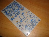
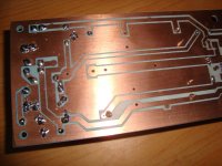
hi all i used the above schema and redrew in eagle to drive two outputs it worked fine and i replaced the irs900d
at least it had no mood swings and worked well all night long playing loud 1 channel with 8 ohms and another with 4 ohms
because i had fried
 most of my outputs thanks to irs900d , one channel i used two irfp250n and the other channel i used
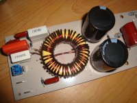
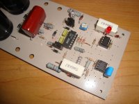
  "my spare smps fets" irfp460 the voltage was +/-70vlts , inductor was 36turns etd28 with 2mm gap, output filter caps were 2.47uf. the switching freq was abt 187khz , i faced no issues with noise because i did a proper layout with star ground.
but irs900d had more clarity than the ucd

more photos to come
Attachments
Last edited:
it's doing really really well. i've hit nearly 120db using the amp without issues.hi paskal have you faced issues with the four channels you made or is it doing well?
the 4 channels is doing stable and robust enough that i've built another amp with 4 more channel driving my dual ported subs. also bridged, but with lower 35v rail voltage. the ported subs have cheaper drivers and are only rated for 600W rms.
if it's based on the same irs900d, then you need a load to kickstart the oscillation. once the oscillation starts you can remove the load. this doesn't happen if the amps are unbridged.hi,,,
Greetings,
i face problem in irs3000, when i bridge the amplifier wont start oscillation,
are you have any solution for this problem,
i'm fixing the problem by using a DC protect circuit after the amp. since there's the DC protect which will disable the relay i just solder a high watt resistor at the relay contact to ground the amp output through the resistor. the DC protect have a turn on delay that gives just enough time for the amp to start oscillation.
once it starts oscillating the amp doesn't care if there's a load or not. it will continue oscillating. at least on my modules. there's no problem if the amp is unbridged, but once you remove the ground by bridging then it won't start oscillation even when the load is connected.
maybe you can try increasing the switching frequency. the irs900d have a higher frequency than 187khz. around 400khz if my memory is correct.post no #2473 at page 248
http://www.diyaudio.com/forums/clas...00-watts-using-2-mosfets-248.html#post3148621
also lorylaci project forum
http://www.hobbielektronika.hu/cikkek/600w-os_d_osztalyu_vegfok.html?pg=1
hi all i used the above schema and redrew in eagle to drive two outputs it worked fine and i replaced the irs900d
at least it had no mood swings and worked well all night long playing loud 1 channel with 8 ohms and another with 4 ohms
because i had fried
but irs900d had more clarity than the ucd
more photos to come
maybe i'll give the circuit a try. got lots of free time nowadays
but irs900d had more clarity than the ucd
Now you passed the basics, here it comes the details. However I tried to explain these details at a dummy level, so more can understand it.
I reccomended you to lower swithcing frequency, and also your filter cutoff frequency, so itt will cut some material at >10kHz. However it is neccessary to lower swithcing freq, because you cannot buy modern (like IRFB4227) FETs.
I reccomend biamping, driving the tweeters with class-B amps, which need lower power.
Also Class D amps have a complex THD versus power curve:
- At lower power noise dominates, this is true for alla mps
- At medium power you have the THD fllor, which is a complex function of your layout, dead-time settings, swithcing noise reduction etc...
- At voltage outputs of about 70-90% of the supply rails a new phenomenon starts kicking it. It is called modulation error. Your amplifier has a input to output propagation delay (sum of the propagation delays of all parts). A Class-D amp has problem producing shortes pulses than the propagation delay.
It can be easily understood: your amplifier feedback loop watches the output and feeds back an error signal to input and so varies inputs so that output should have no error. However its control has a delay, so if it has to use control singals shorter then its operation delay, its starts producing errors.
So if you have a rails of +/-70V then you signal starts to have some distortion over 50-60V, a bit before the supply rails. This is normal. To reduce this it is neccesary to decrease the propagation delay of the amplifier (if it can answer faster,it will produce less error).
I managed this by using a full-bridge with no level shifting (so no extra delay of the leverl shifrter), a much faster comparator, and much faster gate driver IC.
This is the first elvel, to make the amplifier faster. The second level is to use an error amplifier. In the IRS2902 there is a built in error amplifier before the comparator.
Let's get back to the operation of the feedback network: the feedback network feeds back the output to produce an erros signal for the control to fix the output. An error amplifier works in two way:
- At noraml oruput it does nothing, however when modulation error start, it amplifies the error, so the control has an easier job correcting it.
- An input comparator delay is proportional to the input overdrive (whcih corresponds to the error signal). So the error amplifier not only helps by amplifiing error, it also decreases propagation delay. It does a dual job.
Due to the built in error amplifier the IRS2902 can operate at small distrotion up to high modulation indexes. This is some explanation for higher clarity.
Howver UcD is a post-feedback scheme, so the feedback also correct error of the output filter network, like:
- hich frequency boost/cut at some load impedances of the the LC filter (UcD has a much flatter freq response)
- nonlinearities of the output inductor (very bad cores not only dissipiate, but can increase distortion too)
- Output inpedance of the inductor (can be significant at high frequencies)
etc...
Hope you liked this post.
it's doing really really well. i've hit nearly 120db using the amp without issues.
the 4 channels is doing stable and robust enough that i've built another amp with 4 more channel driving my dual ported subs. also bridged, but with lower 35v rail voltage. the ported subs have cheaper drivers and are only rated for 600W rms.
pls try to remove a speaker from one of the channels if there is a signal connected to the input.
by the way what voltage did you use and which fet outputs did you use?
it's still stable. once the oscillation starts the amp doesn't care if there's a load connected or not. if there's no load the amp doesn't start oscillation (even when there's input signal), but it doesn't go unstable.pls try to remove a speaker from one of the channels if there is a signal connected to the input.
by the way what voltage did you use and which fet outputs did you use?
with my modules:
no load, no input signal -> no oscillation, stable
with load, no input signal -> oscillation, stable
no load, with input signal -> no oscillation, stable
with load, with input signal -> oscillation, stable
oscillation, then remove load -> continue oscillation, stable
stable in the sense that the amp draws < 100mA and doesn't heat up, and continue operation as normal once a speaker is connected. i frequently disconnect one side of the subs during EQ process to measure the frequency response of each sub. i have one sub in each corner of the room and EQ them independently.
FET is IRF5615 (150V, 35A).
voltage is +-45V and +-35V. load is 4 ohm (bridged so each module sees 2 ohm).
thanks lorylaci i liked the post.
do you have a clear sounding schema which uses ic ir2110 or ir2011 and not the good irs2092?
or can i substitute lm311 and directly use lt1016 to improve sound quality ?
IR2110 with its 500V limit is originally intended for SMPS gate driver, however it can be used for audio at <200V, but there are better ICs. If you can get IR2010 you should try that (faster).
I have a full-bridge plan with HIP4080A (full-bridge driver with built in comparator) I already shared that somewhere in the forum. I would also reccomend it.
Texas Instruments have some very good new 120V gate drivers, so why not try them in full bridge. Using full brdige lets you use 100V FETs for the same power as 200V ones. I am using FDP3652 FETs, they are really good, and I can get them cheap.
thanks paskal and lorylaci i will post available gate drivers . is it wise to use discreet mode like ucd 2.5 Class D.fromru.com ?
>>> i once used it and it was o.k in terms of sound quality. but the maxx voltage i used was +/- 60vlts although most times i used +/-45vlts
>>> i once used it and it was o.k in terms of sound quality. but the maxx voltage i used was +/- 60vlts although most times i used +/-45vlts
D
Deleted member 148505
thanks for the reply . i am facing serious issues with irs900 both thienchay and detex they work for a short time or a few days and fail i have had three different experiences .in all the above the voltage was
>>> +/- 70vlts about 6amps and filtering caps were 6800uf per rail.
>>>the load was 3ohms to 8 ohms
>>>all the output fets were one pair irfp250n
>>>all the inductor i used was etd 33 or ee 33 , 15turns and 1mm gap on both legs using a piece of CD or DVD disc
>>>switching frequency was 250khz normal on the thienchay and detex layout
two projects had two channels one project had four channels.
i am thinking maybe busspumping, slow fets ("but dismissing it because big proffesional companies powersoft use irfp250n") , non ucd topology or core saturation . please help i am really confused .
i have another irs900 three channels which has survived for one year plus without any issues except bowing fuse when one output of either channel ,a speaker or load is disconnected when the amp is on. all the specs are like the above except the voltage is +/-39vlts.
i will post photos later.
Did your IRS900 fail at startup? If yes it's possible that you have a startup problem described here. Check the time constant of your bootstrap supply...
Since IRS900 doesn't have overcurrent protect, high side latching at startup will cause both mosfets to blow.
thanks lester. i think that is the best explanation. because i had build manojs great amp aud600 three channels with protection board , it worked well and very fine even when using a generator instead of ac from mains. voltage was +/- 60vlts output fets were irfp250n .
but when i did not use the protection board . it failed even at startup even without a load same case as irs900d. and the case was not one board but different experiences.
but when i did not use the protection board . it failed even at startup even without a load same case as irs900d. and the case was not one board but different experiences.
spw52n50c3
Manufacturer: Infineon
Product Category: MOSFET
RoHS: RoHS Compliant Details
Transistor Polarity: N-Channel
Drain-Source Breakdown Voltage: 560 V
Gate-Source Breakdown Voltage: +/- 20 V
Continuous Drain Current: 52 A
Resistance Drain-Source RDS (on): 70 mOhms
Configuration: Single
Maximum Operating Temperature: + 150 C
Mounting Style: Through Hole
Package / Case: TO-247
Packaging: Tube
Fall Time: 10 ns
Minimum Operating Temperature: - 55 C
Power Dissipation: 417 W
Rise Time: 30 ns
Series: xPW52N50
Factory Pack Quantity: 240
Tradename: CoolMOS
Typical Turn-Off Delay Time: 120 ns
Hello
greetings is this mosfet suitable for class d amps as its easily available
made by IFINIEON
warm regards
andrew lebon
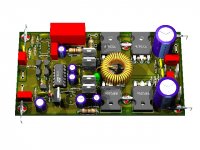
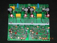
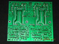
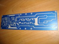
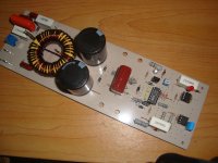
some class d amps in working progress,
triell 3200, detex audio irs3000d, srimodify 3200i.
triell 3200, detex audio irs3000d, srimodify 3200i.
Attachments
- Home
- Amplifiers
- Class D
- UCD 25 watts to 1200 watts using 2 mosfets