You're using IRFP250 which has a high Qg, provide at least 1A aux supply per module.
Looks like the amp is unstable and the mosfets are slightly turning on when the amp is not oscillating. Does each of the irf640 aux supply too far away from the modules?
thanks for the reply but i dont understand the above question.
D
Deleted member 148505
it minimizes the voltage sag to a point that it only drops 1-2 volts during huge bass hits. this is to a sealed 15" sub with only 86 dB sensitivity.
Given that the filtering in the rail supply has low capacitance, I thought that there will be less voltage sag in half bridge because of the bus pumping phenomenon...
 Maybe I should minimize the rail filter capacitance so that the voltage sag won't drop that much?
I have to remeasure the voltage drop of my amp to confirm it, I'll use 2x4700uf 100VDC and 20hz test signal at +-65VDC unloaded rails. If calculated using that parameters with a load of 2 ohms, the increase in voltage should be 17.52VDC when bus pumping occurs.
With my measurement before, the voltage drop at full load when the test signal is 500hz was 15VDC. For my next experiment, the bus pumping should occur, so the rail voltage should not sag but will increase to 2.52VDC.
thanks for the reply but i dont understand the above question.
nevermind, is your amp ok now?
Last edited by a moderator:
Hi Steve,
your schematic does not show any start up path for the upper gate drive supply.
==> A self oscillating amp without such start up path is likely to lock up, especially during turning on.
You can try a 33k (at least 0.5W) resistor from positive power rail to the VB pin of the IR chip.
Your obseravtion of high current draw and blowing fuse is a little bit making me afraid, that you are also struggling with some parasitic effects which provide some uncontrolled gate drive to the upper MosFets even without driver supply.
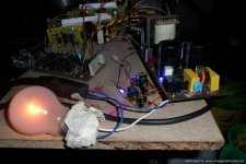
This is adding the unpleasant risk of a heavy defect when experimenting with the additional resistor. To reduce this risk, you should put serial light bulbs (i.e 230V/100W) in the pos and neg supply wires before experimenting.
Good luck
Markus
[/I]
hi choco i did as suggested still no improvement but a bit stable on starting up.

Hi stewin,
Without load(speaker) amp will not oscillate.Provide a dummy load use 1K5/2W or 2K2/2W resistor.
Regards
MANOJ
also manoj the 1k5 is at each output still no change
i think i'll go back to ucd original circuit by etajale or use one power supply for a maxx of two channelsany way my smps worked with the amps and crossover without issue i thank GOD for dimonis sharing the amazing calculation tool diysmps
diysmps
http://www.diyaudio.com/forums/powe...r-4000-a.html?highlight=smps+transformer+tool
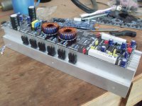
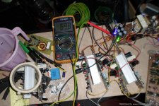
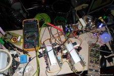
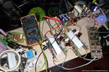
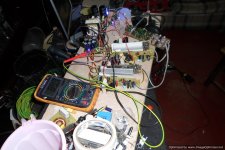
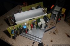
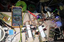
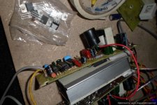
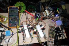
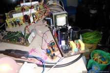
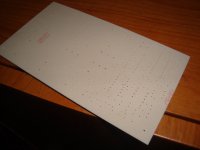
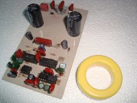
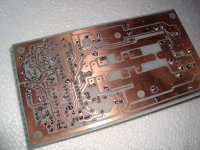
also added small aux dual 6vlts travel phone charger for power supply because the mje 340 2k2 2wts droppers were over heating but every thing works fine even the amps provide i did not disconnect a speaker from any of the four 4 channels . the channel i disconnected a speaker failed after 20 mins even though there was no signal except just power supply. but apart from the above every thing was cool and the no class d noise the photos
Attachments
-
 SAM_3033.JPG928.3 KB · Views: 1,688
 -
 SAM_3020.JPG739.8 KB · Views: 1,200
 -
 SAM_3041.JPG961.2 KB · Views: 1,042
 -
 SAM_3036-Optimized.JPG805.2 KB · Views: 888
 -
 SAM_3030.JPG877 KB · Views: 186
 -
 SAM_2996-Optimized-1.JPG590.9 KB · Views: 232
 -
 SAM_3042-Optimized.JPG842.9 KB · Views: 178
 -
 SAM_3022.JPG857.9 KB · Views: 179
 -
 SAM_3043-Optimized.JPG836.4 KB · Views: 161
 -
 SAM_3019.JPG952.3 KB · Views: 152
Last edited:
thanks man GOD bless you.
what about the class d eecore calculator?.
Last edited:
...to bad that your amp has remaining issues without load.
Seems like we are at the point, were detail measurements would be necessary for proper debugging.
Of course also always an option - (no, I am not proposing it, my engineering soul dislikes this method to much) just randomly varying components / randomly trying small variations of component values...
thanks man GOD bless you.
what about the class d eecore calculator?.
Catch
One program for metal powder ring cores , other - for ferrite cores
Attachments
Catch
One program for metal powder ring cores , other - for ferrite cores
hey dimonis you're the man hi
hi,
greetings,
ir2110 in available in many types of printing then how to find the original ir gate driver i bought 10 gate drivers last week but only 5 is working. another 5 is defect or damage. duplicate gate driver damage the inverter ic or volume low, or dead. then what is the solution for this problem or i will change the gate drive with fair child fan7392.
thanks chocoholic i think it has to do with the feed back or ucd (post filter) is a better way
Hi Stewin,
changing to UcD is in my eyes also just a random variation.
And for sure a variation which is large enough to make it impossible to draw any engineering conclusion from it.
Even if it works in UcD config there is no evidence if the issues of your current version are caused by the working principle or specific implementation details.
Basically your schematic is showing a self oscillator consisting from a rectangle+integrator+hysteresis, which is a well proven traditional configuration for oscillators.
Nevertheless, if you know a bullet proof implementation of UcD then it might be easier to use it rather than debugging your current design.
D
Deleted member 148505
Hi Stewin, how's the sound and what mosfets are you using? My amp is also a derivative of IRAUDAMP1 just like your IRS900. I got very good sound after I used IRFB4227 and used lower gate resistors value (9.1 ohms). Mosfets are not heating too. Minimizing the dead time improves the sound a lot.
Full range sound is much like that of L25D boards I have.
Full range sound is much like that of L25D boards I have.
D
Deleted member 148505

working in progress irs3000 detex audio.
Already mounted this amp and have had several problems with it
what is the problem u faced with irs3000?
This circuit oscillates with only the audio signal at the input and output load.
Rather circuits based on IRS2092 or the crystal oscillator - according to the scheme already posted this forum.
Stewin, try it with separate bias supply for each of the module first before scrapping your work haha,..
the amp sound is excellent , except the issue of powering the amp without a speaker load everything is o.k.
bias supply you mean the 12vlts to feed the ir2110?
- Home
- Amplifiers
- Class D
- UCD 25 watts to 1200 watts using 2 mosfets