Hello all,
I m quite new here but quite interested in this topic.
My history: I have a masters degree in power electronics, about 10 years experience in power supply engineering. Starting many years ago, I 've done some SIMETRIX work on sigma delta self-oscillation with feedback before filter, built one 5kW subwoofer amp based on this very easy control topology using 1200V APT IGBTs at 600V bus / 20kHz (still working - pics avail.), then come over to play around with UCD style post filter feedback control to try to get a feeling on how it would behave on things like step
response, no load, slew rate etc.... in transient sim...
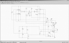
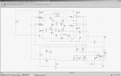
..attached you can find "my approach" to UCD in "block style" - not on component level - in SIMETRIX. Its a 180V bus powered full bridge using 200V components at ~470kHz capable of giving >3kW at 4 Ohm, much like UCD 2K. FETs in SIM are simplified by switches (20mOhm / 1MOhm), series schottky is missing (no effect for control loop analysis, but for switching losses), antiparallel diode would be 200V ultrafast or 300V carbide in reality. S9 and R4 are only a replacement for a comparator so R4 voltage will be
square either 0 or 12V. R10, C5 will give about 200 ns to simulate delay between comparator inputs crossing and actual bridge nodes moving. L3 / R2 is the load impedance to play around with - can be ohmic or "loudspeaker" or passive X-over network or....
Result: works in simulation.
Next step:
-> I invented some new control topology that I will call self oscillating Class D (SOCD). <-
Goal: PA full bridge amp using 180 V bus, nearly same performance as UCD in things like step response, output resistance / damping, frequ. response >20.000Hz.... gain 35dB, workable from 2 Ohms to 32 Ohms at up to 120VRMS output voltage and fully stable at no load with slight overshoot accepted at no load /square wave input (which is not really the typical application....). Less frequency decline than UCD at very low or very high duty cycles. Still self-oscillating, but no need to infringe bruno's patent should it be built (actually planning on this).
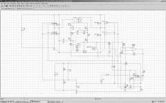
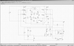
You can find the "block-style" simulation file attached. TX 1 is a transformer on MPP material instead of 2 chokes. Why: Only 70.7 % turns is needed for the same "effective" inductance if 2 chokes wound on 1 core. Have only one component instead of 2! (Core would still be as heavy as 2 single inductors cores for the sum energy stored doesn't change). One winding is 13.3uH, but acts like 26.5uH. L4 / R12 is an air coil. It can be used to tune the oscillation freq. just by mechanically pulling and pushing it. R36, R13 and especially R35 could face some real watts during bursts of 5-digit frequency waves at high power, so use 10W non inductive types, although average power will be much lower. The resistors help to improve transient response at very high ohmic loads.
Result: Sim results look quite ok, goals more or less achieved. The air coil will also give an effective 4th order filter for higher harmonics >1MHz, so EMI will be much improved over single LC filter.
Why am I posting this:
I d like to hear and test this thing, but I need someone to help with layouting and soldering / assembling this in 2 channels for me and send over 1 stereo unit to me. My part would be:
Define schematics and define actual components, define air coil dimensions, help to get and provide components like hi side driver / FETS / diodes / foil caps etc., help and give (remote) advice on layout, power up the unit carefully in my lab and send back final "rework instruction" to you so you can really get to see it working.
Anybody here interested?
I m quite new here but quite interested in this topic.
My history: I have a masters degree in power electronics, about 10 years experience in power supply engineering. Starting many years ago, I 've done some SIMETRIX work on sigma delta self-oscillation with feedback before filter, built one 5kW subwoofer amp based on this very easy control topology using 1200V APT IGBTs at 600V bus / 20kHz (still working - pics avail.), then come over to play around with UCD style post filter feedback control to try to get a feeling on how it would behave on things like step
response, no load, slew rate etc.... in transient sim...
..attached you can find "my approach" to UCD in "block style" - not on component level - in SIMETRIX. Its a 180V bus powered full bridge using 200V components at ~470kHz capable of giving >3kW at 4 Ohm, much like UCD 2K. FETs in SIM are simplified by switches (20mOhm / 1MOhm), series schottky is missing (no effect for control loop analysis, but for switching losses), antiparallel diode would be 200V ultrafast or 300V carbide in reality. S9 and R4 are only a replacement for a comparator so R4 voltage will be
square either 0 or 12V. R10, C5 will give about 200 ns to simulate delay between comparator inputs crossing and actual bridge nodes moving. L3 / R2 is the load impedance to play around with - can be ohmic or "loudspeaker" or passive X-over network or....
Result: works in simulation.
Next step:
-> I invented some new control topology that I will call self oscillating Class D (SOCD). <-
Goal: PA full bridge amp using 180 V bus, nearly same performance as UCD in things like step response, output resistance / damping, frequ. response >20.000Hz.... gain 35dB, workable from 2 Ohms to 32 Ohms at up to 120VRMS output voltage and fully stable at no load with slight overshoot accepted at no load /square wave input (which is not really the typical application....). Less frequency decline than UCD at very low or very high duty cycles. Still self-oscillating, but no need to infringe bruno's patent should it be built (actually planning on this).
You can find the "block-style" simulation file attached. TX 1 is a transformer on MPP material instead of 2 chokes. Why: Only 70.7 % turns is needed for the same "effective" inductance if 2 chokes wound on 1 core. Have only one component instead of 2! (Core would still be as heavy as 2 single inductors cores for the sum energy stored doesn't change). One winding is 13.3uH, but acts like 26.5uH. L4 / R12 is an air coil. It can be used to tune the oscillation freq. just by mechanically pulling and pushing it. R36, R13 and especially R35 could face some real watts during bursts of 5-digit frequency waves at high power, so use 10W non inductive types, although average power will be much lower. The resistors help to improve transient response at very high ohmic loads.
Result: Sim results look quite ok, goals more or less achieved. The air coil will also give an effective 4th order filter for higher harmonics >1MHz, so EMI will be much improved over single LC filter.
Why am I posting this:
I d like to hear and test this thing, but I need someone to help with layouting and soldering / assembling this in 2 channels for me and send over 1 stereo unit to me. My part would be:
Define schematics and define actual components, define air coil dimensions, help to get and provide components like hi side driver / FETS / diodes / foil caps etc., help and give (remote) advice on layout, power up the unit carefully in my lab and send back final "rework instruction" to you so you can really get to see it working.
Anybody here interested?
Attachments
Last edited by a moderator:
I've been simulating a similar full bridge since the fall. Mine looks very much the same as yours except the filter is conventional and I run at up to 60V, single supply. The only reason (but there are a few more advantages too....) to do a full bridge is to be able to run off a single supply, IMHO. I'd like to understand the output filter in the second picture a bit more.
The bridged to single ended conversion by the opamp, and I have the same thing, bothers me since the only reason it is there is to provide the differential to SE conversion and no gain. I wish there was a way to do this with passives.....Yes, I know....a transformer.
I think your design should work quite well.
BK
@stoc005: TX1, C18, C9 is a 1st order LC slightly damped by R13. Air coils, C17, R36 is a low impedance resonator that will set the resonant frequency by well defined phase decay - so resonant freq. is (almost) independent on output load as long as load does not get significantly lower than 1.5 Ohm or so... evrything optimized by many sim runs.. R35 C7 is a "bonus" damping and can be avoided if no load step response is no issue (if focus application is only 2 - 8 Ohms...)
the opamp doesn't really worry me since its cost is bout one "buck" .. as you call it over there.. i'm more worried on getting a precise 100V / us comparator
the opamp doesn't really worry me since its cost is bout one "buck" .. as you call it over there.. i'm more worried on getting a precise 100V / us comparator
Hello all,
I m quite new here but quite interested in this topic.
My history: I ve a masters degree in power electronics, about 10 years ex in power supply engineering. Starting many years ago, I ve done some SIMETRIX work on sigma delta self-oscillation with feedback be4 filter, built one 5kW subwoofer amp based on this very easy control topology using 1200V APT IGBTs at 600V bus / 20kHz many years ago (still working - pics avail.), then come over to play around with UCD style post filter feedback control to try to get a feeling on how it would behave on things like step
response, no load, slew rate etc.... in transient sim...
..attached you can find "my approach" to UCD in "block style" - not component level - in SIMETRIX. Its a 180V bus powered full bridge using 200V components at ~470kHz capable of giving >3kW at 4 Ohm, much like UCD 2K. FETs in SIM are simplified by switches (20mOhm / 1MOhm), series schottky is missing (no effect for control loop analysis, but for switching losses), antiparallel diode would be 200V ultrafast or 300V carbide in reality. S9 and R4 are only a replacement for a comparator so R4 voltage will be
square either 0 or 12V. R10, C5 will give about 200 ns to simulate delay between comparator inputs crossing and actual bridge nodes moving. L3 / R2 is the load impedance to play around with - can be ohmic or "loudspeakeric" or passive X-over network or....
Result: works in simulation.
Next step: I invented some new control topology that I will call self oscillating Class D (SOCD).
Goal: PA full bridge amp using 180 V bus, nearly same performance as UCD in things like step response, output resistance / damping, frequ. response >30.000Hz.... gain 35dB, workable from 2 Ohms to 32 Ohms at up to 120VRMS output voltage and fully stable at no load with slight overshoot accepted at no load /square wave input (which is not really
the typical application....). Less frequency decline than UCD at very low or very high duty cycles. Still self-oscillating, but no need to infringe bruno's patent should it be built (actually planning on this).
You can find the "block-style" simulation file attached. TX 1 is a transformer on MPP material instead of 2 chokes. Why: Only 70.7 % turns is needed for the same "effective" inductance if 2 chokes wound on 1 core. Have only one component instead of 2. (Core would still be as heavy as 2 single inductors cores coz the sum energy stored equals 2 inductors). One winding is 13.3uH, but acts like 26.5uH. L4 / R12 is an air coil. It can be used to tune the oscillation f. w/o soldering just by mechanically pulling and pushing it. R36, R13 and especially R35 could face some real watts during bursts of 5-digit frequency waves at high power, so use 10W non inductive
types, although average power will be much lower. The resistors help to improve transient response at very high ohmic loads.
Result: Sim results look quite ok, goals more or less achieved. The air coil will also give an effective 4th order filter for higher harmonics >1MHz, so EMI will be much improved over single LC filter.
Why am I posting this:
I d like to hear and test this thing, but as I am quite on the lazy side, I need someone to do some layouting and soldering / assembling this in 2 channels for me and send over 1 stereo unit to me. My part would be:
Define schematics and define actual components, define air coil dimensions, help to get and provide components like hi side driver / FETS / diodes / foil caps etc., help and give (remote) advice on layout, power up the unit carefully in my lab and send back final "rework instruction" to you so you can really get to see it working. AND as a special bonus: I'd send you over a 5kW PFC powered 3 ph input isolated 177Vdc Power supply for operating the amp. (It will actually be 3 single phase telcom rectifiers with series'sed outputs, so would also work on just one "household" phase - with less output power).
Anybody here interested?
I would be interested in building this baby.
mail me at savu_silviu@hotmail.com for more details
PS. hope you live in europe
Best regards,
Savu Silviu
the opamp doesn't really worry me since its cost is bout one "buck" .. as you call it over there.. i'm more worried on getting a precise 100V / us comparator
It is even possible to build this schematic without any opamps, feeding "differential" bridge output to the differential comparator inputs via resistive voltage dividers (with appropriate "phase lead" networks)...
Wounding full bridge output filter on the single core is a known trick, but using of 4th order LC filter to set selfoscillation frequency is really new and good idea!
")
I have developed my own self-oscillating topology too, at the voltage and power levels that you mention. I more or less managed to solve all the problems related to making it work in the real world and making manufacturing not too complex.
If you do THD analysis, you may notice that neither the 4th order output filter nor less than 1:2 oscillation frequency drop are good ideas. A second active pole may be a good idea, though.
Feding carrier residual to the comparator through op-amps is not a good idea either. I had noise immunity problems (the circuit disturbing itself due to EMI) in some of my early prototypes. There don't seem to be many ways to make it work fine, only a few.
Don't forget about parasitics when modelling output filter. Parasitic L and C will reduce the quality of the carrier residual waveform and degrade THD.
"If you do THD analysis, you may notice that neither the 4th order output filter nor less than 1:2 oscillation frequency drop are good ideas. A second active pole may be a good idea, though.
Feding carrier residual to the comparator through op-amps is not a good idea either. I had noise immunity problems (the circuit disturbing itself due to EMI) in some of my early prototypes. There don't seem to be many ways to make it work fine, only a few.
Don't forget about parasitics when modelling output filter. Parasitic L and C will reduce the quality of the carrier residual waveform and degrade THD. "
I think THD is mainly dependent on blanking time and that is dependent on how well timed you can get the switches to work. I think I can't do any THD analysis just by simulation.
I also think its possible to even avoid the opamp, but have not worked out this idea...
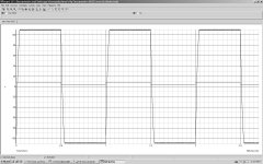
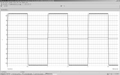
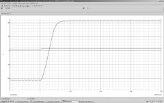
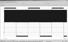
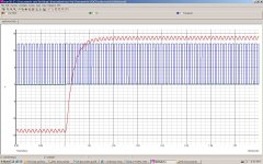
Attached you can find some nice step response results of SOCD simulation. Input = Square 2Veff = 2 Vpk, Output = 2, 4, or 8 Ohms resp.
Feding carrier residual to the comparator through op-amps is not a good idea either. I had noise immunity problems (the circuit disturbing itself due to EMI) in some of my early prototypes. There don't seem to be many ways to make it work fine, only a few.
Don't forget about parasitics when modelling output filter. Parasitic L and C will reduce the quality of the carrier residual waveform and degrade THD. "
I think THD is mainly dependent on blanking time and that is dependent on how well timed you can get the switches to work. I think I can't do any THD analysis just by simulation.
I also think its possible to even avoid the opamp, but have not worked out this idea...
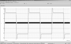
Attached you can find some nice step response results of SOCD simulation. Input = Square 2Veff = 2 Vpk, Output = 2, 4, or 8 Ohms resp.
Attachments
For most of you don't like the OPAMP within the feedback, I just eliminated it. Result is attached. Still working - same behavior...

You will need op-amps for implementing active poles, the trick is to wire them in such a way that the circuit does not rely on them much above 20khz.
May I rephrase your sentence?
I would say "the trick is to wire them in such a way that the circuit does not rely on them near Fo of the output LC filter". I am right? Also, is the usual integrator an example of the active pole filter? I have tried to read about it somewhere in Internet/Wikipedia, but it is usually connected with too complex mathematics for me...


@EVA: Why would I need active poles?
Explanation in attached image...
Attachments
But what is this good for? Output impedance at low frequencies? Isn't it better to have constant loop gain throughout the audio band?
I would say, in this case each decides on its own, what is better...
But again, 25dB loop gain is too low for me...
@81bas: After some calculation and simulation, I came to the conclusion that the loop gain in my circuit is about 20 (equals 26dB) So you are quite right in assessing my circuit! You must be quite an expert! How did you calculate? I divided output pk pk amplitude by (comparator input peak peak ripple times audio frequency voltage gain). e.g. 360 / (0.32 x 56) = 20
@81bas: After some calculation and simulation, I came to the conclusion that the loop gain in my circuit is about 20 (equals 26dB) So you are quite right in assessing my circuit! You must be quite an expert! How did you calculate? I divided output pk pk amplitude by (comparator input peak peak ripple times audio frequency voltage gain). e.g. 360 / (0.32 x 56) = 20
oh, I am not an expert at all
I have seen this value in previously attached image, and supposed that most of UCD designs will have the same loop gain too... However, I completely agree with your way to calculate the loop gain in UCD. The key point here is the amount of switching ripple at the comparator input, as you mentioned... I think also, that increasing the switching frequency will increase the loop gain of UCD, since amount of the residual ripple will be lower!
SOCD - implementing the pole...
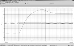
So I implemented a pole @ ~20kHz (C4, R6). Of course w/o any opamp!!
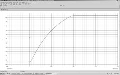
Now the calculated loop gain is ~ 52dB from DC to ~1kHz, then falling linearly to ~ 26dB @20k. I think that is quite ok for ultra-high bass and lower-mid-area damping factor.
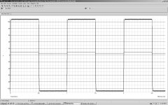
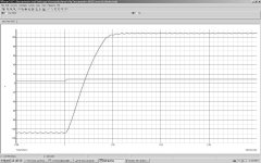
Step response: You can see from the small signal response: it is - of course - nearly perfect. Big signal step response looks like slight instability for the first glance, but it is not: If higher slew rate is demanded than output filter can deliver, the regulator loop is "overloaded" and the high loop gain "pole loaded" regulator will "remember" missed volt-second product during ascent or descent of output voltage and then answer with the overshoot. This is NOT instability. It will occur at high slew rates and can be more or less avoided by placing a bandwith limiting input filter in front of the amplifier (like 5Hz - 25kHz 2nd order, which I recommend for PA amplifier....)
So I implemented a pole @ ~20kHz (C4, R6). Of course w/o any opamp!!
Now the calculated loop gain is ~ 52dB from DC to ~1kHz, then falling linearly to ~ 26dB @20k. I think that is quite ok for ultra-high bass and lower-mid-area damping factor.
Step response: You can see from the small signal response: it is - of course - nearly perfect. Big signal step response looks like slight instability for the first glance, but it is not: If higher slew rate is demanded than output filter can deliver, the regulator loop is "overloaded" and the high loop gain "pole loaded" regulator will "remember" missed volt-second product during ascent or descent of output voltage and then answer with the overshoot. This is NOT instability. It will occur at high slew rates and can be more or less avoided by placing a bandwith limiting input filter in front of the amplifier (like 5Hz - 25kHz 2nd order, which I recommend for PA amplifier....)
Attachments
So I implemented a pole @ ~20kHz (C4, R6). Of course w/o any opamp!!
Now the calculated loop gain is ~ 52dB from DC to ~1kHz, then falling linearly to ~ 26dB @20k. I think that is quite ok for ultra-high bass and lower-mid-area damping factor.
Cool!
I am not sure, whether it will work for real world comparator, but anyway...Could you please say, how big is the difference in switching frequency between "zero" and "near clipped" output state in your simulations? Usually there is a 2:1 frequency drop, as Eva said, but it is for "normal" UCD...
Last edited:
- Status
- This old topic is closed. If you want to reopen this topic, contact a moderator using the "Report Post" button.
- Home
- Amplifiers
- Class D
- New self oscillating post filter feedback topology...