@81bas: It 'll have to work with real world comparator, for I gonna build it. I 've never seen a 2:1 drop with my topology, neither SOCD nor SOCD pole, only a little drop. Over the WE I can't simulate because there is no "home version" of simetrix! But I will get back on this next week if I don't forget to. Unfortunately the pole implementation has increased the frequency slightly over 500k...hmm...
Do you think this is the way a pole loaded circuit should look like / behave?
If I can get the comparator to work with only ~17mV switching residual, and also the power stage, do you think this will be a good amp?
Do you think this is the way a pole loaded circuit should look like / behave?
If I can get the comparator to work with only ~17mV switching residual, and also the power stage, do you think this will be a good amp?
@81bas: It 'll have to work with real world comparator, for I gonna build it. I 've never seen a 2:1 drop with my topology, neither SOCD nor SOCD pole, only a little drop. Over the WE I can't simulate because there is no "home version" of simetrix! But I will get back on this next week if I don't forget to. Unfortunately the pole implementation has increased the frequency slightly over 500k...hmm...
Do you think this is the way a pole loaded circuit should look like / behave?
If I can get the comparator to work with only ~17mV switching residual, and also the power stage, do you think this will be a good amp?
First of all, I wonder, that you have only a little frequency drop
 can you please check it on some sinusoidal signal? Seems in case of 4th order output filter, the UCD switching frequency completely depends on the filter's corner frequency...
 17mV at comparator inputs should suffice for most types of comparators, I think, but can produce some delay and noise... LT1016 for example needs about 3-4mV overdrive to completely change it's output state. LM319 needs about 1-2mV. (taken from datasheet diagrams) Layout will be critical at such low input voltage too...
I still dislike too low loop gain at high frequencies (26dB you said), but maybe it is not so dramatical at all...
"First of all, I wonder, that you have only a little frequency drop can you please check it on some sinusoidal signal?"
As I said I can check but next week. Also the frequency is too high now (~650k @zero output) - any idea how the pole implementation could have risen it? need to do some re-adjustment. But using schottky freewheeling diodes (like Vishay V30200 - almost no reverse recovery losses) even 650 kHz could be realistic - don't you think?
"Seems in case of 4th order output filter, the UCD switching frequency completely depends on the filter's corner frequency..."
This is not UCD! I call it "SOCD pole".
"17mV at comparator inputs should suffice for most types of comparators, I think, but can produce some delay and noise... LT1016 for example needs about 3-4mV overdrive to completely change it's output state. LM319 needs about 1-2mV. (taken from datasheet diagrams) Layout will be critical at such low input voltage too..." Yeah LM310 looks quite good, is there an even faster device? - I fear that the devices tend to get slower with less input overdrive....
"I still dislike too low loop gain at high frequencies (26dB you said), but maybe it is not so dramatical at all... " I don't think there is many ways to increase loop gain at the uppermost frequencies...other than megaherz switching...But I don't think too many guys can hear 20kHz, and almost no one can hear slight distortion at that frequency coming from the amp. Especially when the speakers are overblown at a stage event and thousands of drunken people are "raving" or "headbanging"...lool
BTW: I didnt find out how to quote here?
First of all, I wonder, that you have only a little frequency drop
17mV at comparator inputs should suffice for most types of comparators, I think, but can produce some delay and noise... LT1016 for example needs about 3-4mV overdrive to completely change it's output state. LM319 needs about 1-2mV. (taken from datasheet diagrams) Layout will be critical at such low input voltage too...
Oh ohh.... the frequency drop issue is very complicated. There is indeed big drop at the very end of the duty cycle. Need to investigate much more. It also depends on the delay time. But why is frequency drop sooo bad? I think Eva doesn't like frequency drop?! I think it can be even good because the pulses will too early become unrealistically short, if the frequency stays constant. E.g. 500kHz 95% duty => 100ns pulses, 250 kHz -> 200 ns
But why is frequency drop sooo bad? I think Eva doesn't like frequency drop?! I think it can be even good because the pulses will too early become unrealistically short, if the frequency stays constant. E.g. 500kHz 95% duty => 100ns pulses, 250 kHz -> 200 ns
well, maybe it is not "sooo" bad, but it has nothing good for sound quality definitely, I would say
It is needed to avoid too early frequency drop somehow, but seems it is inavoidable at the very end of the duty cycle in phase controlled oscillation 
So hello again, some months have passed and I am now putting together the final schematic with layout planned for autumn. Main Comparator will be MAX 961 (need 2 opposite outputs with perfect delay matching for full bridge, need ultra-high speed even at low overdrive), Input prefilter will be 2nd order bandpass 10 Hz - 25khz (OPA134).
As a main choke I want to use Magnetics "58083-A2" or Arnold "HF1570060-2", 2 cores stacked for one full bridge channel, total 18 turns. This gives 52uH (or 2 x 13uH) My goal is to meet or beat LAB fP6400 under all power conditions, so I need to provide 3.2 kW burst sine waves, 8ms, 1kHz at 2 Ohms load (EIAJ burst power test at 2 Ohms is definitely the worst case for the magnetic calculation). This condition needs rms output current of 40A (-> e.g. coil peak current ~60A). So on ~140 oersteads, H-Flux 60 u core will still have ~50% permeability left. And thats by far the worst case design point. Any better idea / opinion?
As a main choke I want to use Magnetics "58083-A2" or Arnold "HF1570060-2", 2 cores stacked for one full bridge channel, total 18 turns. This gives 52uH (or 2 x 13uH) My goal is to meet or beat LAB fP6400 under all power conditions, so I need to provide 3.2 kW burst sine waves, 8ms, 1kHz at 2 Ohms load (EIAJ burst power test at 2 Ohms is definitely the worst case for the magnetic calculation). This condition needs rms output current of 40A (-> e.g. coil peak current ~60A). So on ~140 oersteads, H-Flux 60 u core will still have ~50% permeability left. And thats by far the worst case design point. Any better idea / opinion?
Which mosfets do you plan to use? Driver?
IRFP4668, series schottky 20V 60A and antiparallel V30200C
Level-shifter: IRS2011, actual driver: MIC4421 (high side driver floating), very low-ohmic gating circuitry required to ***-kick IRFP4668 - this one is quite sluggish...
Frequency drop is neither good or bad on itself, it's just required to keep carrier residual amplitude as constant as possible at the input of the comparator to make the open-loop transfer characteristic linear.
Too much or too little frequency drop translate into sub-optimal open-loop linearity.
A good frequency drop behavior seems to be a 2:1 smooth drop from 0V to -1dB from clipping. Then propagation delay will show up and cause additional drop in the last dB of output.
Adding op-amps in the carrier residual feedback path (from output to comparator) is not good because delay, phase shift, and some waveform distortion are added, resulting in worse open-loop linearity and lower than expected oscillation frequency. This is something easily measurable, not the usual myth. Also, using many parts in this critical feedback path makes the circuit more likely to disturb itself with its own EMI. I use two feedback loops to allow for proper signal processing without compromising carrier residual quality.
So just let me copy some discussion from another thread over to here:
savu:
so practicaly, every class d amp that has a feedback after the filter and its selfoscilating is a UCD amp
thanks Pafi
Pafi:
Yes, if oscillation is made by phase shift (not hysteresis). But read the statements of the patent, if you want to know exactly!
ViennaTom (=me): "so practicaly, every class d amp that has a feedback after the filter and its selfoscilating is a UCD amp"
-> I dont really think so, coz the UCD patent exactly describes the RC feedback circuitry on comparator input to obtain controlled selfoscillation.
quote:
"the control circuit comprises a first element in the form of a resistor, for controlling said gain and a second element, in the form of a capacitance in series with a resistor, for controlling said alternately switching"
I have invented a different self-oszillation post filter feedback topology. The "second element" is not part of it, at least not in this form. So thats why I claim that my circuit is not UCD covered.
New self oscillating post filter feedback topology...
Also, the feedback transfer function H(s) described in the patent is different in my case as a consequence.
This topology is not "rocket-science", and it has the drawback of the additional air coil, but it can be optimized to work well over a wide load impedance / phase range. I m currently working to realize this as a full bridge with 175V bus....
Pafi:
I dont really think so, coz the UCD patent exactly describes the RC feedback circuitry on comparator input to obtain controlled selfoscillation.
quote:
"the control circuit comprises a first element in the form of a resistor, for controlling said gain and a second element, in the form of a capacitance in series with a resistor, for controlling said alternately switching" This is just the 3rd claim (wich is only the subclaim of the 2nd), but if a circuit meets any of the claims, then it is covered by the patent.
It's useless to alternate the feedback network, the 1st claim still covers it.
Sorry!
ViennaTom: @Pafi:
I see your point, think I need to check this into more detail but for today i m too tired....
Just assume, u re right, then why is there so much talking of the specific RC-circuit and its transfer function within US 7113038 B2 ? Is this patent valid for Europe also (hope not)? and how come one guy can get such a general patent? Doesn't it look like, for example, Bill Gates or another guy suddenly claiming patent for ALL operating systems..
savu:
@ Thomas
He cannot, unless he bribes the right people with the right amount (witch i think that Mr. Bruno didn't do).
PS: happy to hear that you're amp is in the final stages.
regards,
savu
ViennaTom:
@savu:
No, my amp is not in the final stage - with layout and building / power up the most work is still in front. If the patent is as powerful and general as I fear it is, my idea is worthless anyway (need still to check this).... I will continue only if it make sense.....
savu:
@ Thomas ...
The patent shouldn't be that general.
But hope that you're amp will be a success.
regards,
savu

savu:
so practicaly, every class d amp that has a feedback after the filter and its selfoscilating is a UCD amp
thanks Pafi
Pafi:
Yes, if oscillation is made by phase shift (not hysteresis). But read the statements of the patent, if you want to know exactly!
ViennaTom (=me): "so practicaly, every class d amp that has a feedback after the filter and its selfoscilating is a UCD amp"
-> I dont really think so, coz the UCD patent exactly describes the RC feedback circuitry on comparator input to obtain controlled selfoscillation.
quote:
"the control circuit comprises a first element in the form of a resistor, for controlling said gain and a second element, in the form of a capacitance in series with a resistor, for controlling said alternately switching"
I have invented a different self-oszillation post filter feedback topology. The "second element" is not part of it, at least not in this form. So thats why I claim that my circuit is not UCD covered.
New self oscillating post filter feedback topology...
Also, the feedback transfer function H(s) described in the patent is different in my case as a consequence.
This topology is not "rocket-science", and it has the drawback of the additional air coil, but it can be optimized to work well over a wide load impedance / phase range. I m currently working to realize this as a full bridge with 175V bus....
Pafi:
I dont really think so, coz the UCD patent exactly describes the RC feedback circuitry on comparator input to obtain controlled selfoscillation.
quote:
"the control circuit comprises a first element in the form of a resistor, for controlling said gain and a second element, in the form of a capacitance in series with a resistor, for controlling said alternately switching" This is just the 3rd claim (wich is only the subclaim of the 2nd), but if a circuit meets any of the claims, then it is covered by the patent.
It's useless to alternate the feedback network, the 1st claim still covers it.
Sorry!
ViennaTom: @Pafi:
I see your point, think I need to check this into more detail but for today i m too tired....
Just assume, u re right, then why is there so much talking of the specific RC-circuit and its transfer function within US 7113038 B2 ? Is this patent valid for Europe also (hope not)? and how come one guy can get such a general patent? Doesn't it look like, for example, Bill Gates or another guy suddenly claiming patent for ALL operating systems..
savu:
@ Thomas
He cannot, unless he bribes the right people with the right amount (witch i think that Mr. Bruno didn't do).
PS: happy to hear that you're amp is in the final stages.
regards,
savu
ViennaTom:
@savu:
No, my amp is not in the final stage - with layout and building / power up the most work is still in front. If the patent is as powerful and general as I fear it is, my idea is worthless anyway (need still to check this).... I will continue only if it make sense.....
savu:
@ Thomas ...
The patent shouldn't be that general.
But hope that you're amp will be a success.
regards,
savu
So to sum up:
I found out that there even is a world patent application (!) on UCD. It looks claim 1 really tries to cover all post filter self oscillator topologies without hysteresis WORLDWIDE (!!) Can that be real?
Guys, whats your opinion? I's the patent really that general? I need more opinions...
BTW, did anyone investigate into a post-filter feedback self-oscillator control topology using hysteretic oscillation instead of phase osc.? Is there any big drawbacks?
So to sum up:
I found out that there even is a world patent application (!) on UCD. It looks claim 1 really tries to cover all post filter self oscillator topologies without hysteresis WORLDWIDE (!!) Can that be real?
Guys, whats your opinion? I's the patent really that general? I need more opinions...
BTW, did anyone investigate into a post-filter feedback self-oscillator control topology using hysteretic oscillation instead of phase osc.? Is there any big drawbacks?
Yes, the MUETA amplifier used post-filter NFB in the audio band, but used the filter capacitor ripple current to derive the feedback into the hysteretic comparator to define the oscillation. There was an interesting paper about it at an AES conference, but nothing much seems to have come of it.
So to sum up:
I found out that there even is a world patent application (!) on UCD. It looks claim 1 really tries to cover all post filter self oscillator topologies without hysteresis WORLDWIDE (!!) Can that be real?
Guys, whats your opinion? I's the patent really that general? I need more opinions...
Are you planning to go for a commercial roll out?
Regarding DIY I never heard that Bruno would make much trouble - or simply contact him directly.
@Ouboros: Thats exactly what I did in my newest simulation and it seems to work - basically I used UCD style circuit, but with hysteretic comparator and replaced the phase-shifting RC feedback circuit by simple C... Ill continue to compare this to my currently favorite topology whn I have time
@Choco: On pure DIY, no patent holder can makr trouble. Truth is, I'd like to start a commercial series, but need to be sure to hurt no existing patent.
(Which is only one of the many problems to avoid....)
@Choco: On pure DIY, no patent holder can makr trouble. Truth is, I'd like to start a commercial series, but need to be sure to hurt no existing patent.
(Which is only one of the many problems to avoid....)
Hello all,
I m quite new here but quite interested in this topic.
My history: I ve a masters degree in power electronics, about 10 years ex in power supply engineering. Starting many years ago, I ve done some SIMETRIX work on sigma delta self-oscillation with feedback be4 filter, built one 5kW subwoofer amp based on this very easy control topology using 1200V APT IGBTs at 600V bus / 20kHz many years ago (still working - pics avail.), then come over to play around with UCD style post filter feedback control to try to get a feeling on how it would behave on things like step
response, no load, slew rate etc.... in transient sim...
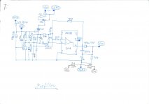
..attached you can find "my approach" to UCD in "block style" - not component level - in SIMETRIX. Its a 180V bus powered full bridge using 200V components at ~470kHz capable of giving >3kW at 4 Ohm, much like UCD 2K. FETs in SIM are simplified by switches (20mOhm / 1MOhm), series schottky is missing (no effect for control loop analysis, but for switching losses), antiparallel diode would be 200V ultrafast or 300V carbide in reality. S9 and R4 are only a replacement for a comparator so R4 voltage will be
square either 0 or 12V. R10, C5 will give about 200 ns to simulate delay between comparator inputs crossing and actual bridge nodes moving. L3 / R2 is the load impedance to play around with - can be ohmic or "loudspeakeric" or passive X-over network or....
Result: works in simulation.
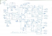
Next step: I invented some new control topology that I will call self oscillating Class D (SOCD).
Goal: PA full bridge amp using 180 V bus, nearly same performance as UCD in things like step response, output resistance / damping, frequ. response >30.000Hz.... gain 35dB, workable from 2 Ohms to 32 Ohms at up to 120VRMS output voltage and fully stable at no load with slight overshoot accepted at no load /square wave input (which is not really
the typical application....). Less frequency decline than UCD at very low or very high duty cycles. Still self-oscillating, but no need to infringe bruno's patent should it be built (actually planning on this).
You can find the "block-style" simulation file attached. TX 1 is a transformer on MPP material instead of 2 chokes. Why: Only 70.7 % turns is needed for the same "effective" inductance if 2 chokes wound on 1 core. Have only one component instead of 2. (Core would still be as heavy as 2 single inductors cores coz the sum energy stored equals 2 inductors). One winding is 13.3uH, but acts like 26.5uH. L4 / R12 is an air coil. It can be used to tune the oscillation f. w/o soldering just by mechanically pulling and pushing it. R36, R13 and especially R35 could face some real watts during bursts of 5-digit frequency waves at high power, so use 10W non inductive
types, although average power will be much lower. The resistors help to improve transient response at very high ohmic loads.
Result: Sim results look quite ok, goals more or less achieved. The air coil will also give an effective 4th order filter for higher harmonics >1MHz, so EMI will be much improved over single LC filter.
Why am I posting this:
I d like to hear and test this thing, but as I am quite on the lazy side, I need someone to do some layouting and soldering / assembling this in 2 channels for me and send over 1 stereo unit to me. My part would be:
Define schematics and define actual components, define air coil dimensions, help to get and provide components like hi side driver / FETS / diodes / foil caps etc., help and give (remote) advice on layout, power up the unit carefully in my lab and send back final "rework instruction" to you so you can really get to see it working. AND as a special bonus: I'd send you over a 5kW PFC powered 3 ph input isolated 177Vdc Power supply for operating the amp. (It will actually be 3 single phase telcom rectifiers with series'sed outputs, so would also work on just one "household" phase - with less output power).
Anybody here interested?
Hi Tom
I appreciate the design, however could you please help me understand some details about the modulator working:
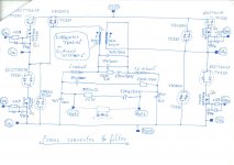
1. The output filter is basically a 2 cascade LC filters, the first is resonating around 30kHz and slightly snubbered, so that it creates just-below 180degrees phase shift.
2. the second LC section provides another steep phase shift at much higher frequencies, so that the phase crosses 180 degrees at the intended switching frequency (250kHz or so).
3. The feedback network does not provide any phase shift, just stay far enough from UCD patent.
If the above analysis is OK, then how about the extra delay through comparator, possible level shifter, driver and switching tage itself?
The realistic 200ns propagation delay at this power already provides around 8 deg.@100kHz phase shift. What is the filter phase shift at 100kHz for this modulator (no load condition)?
Am I right that the output filter keeps close to 180 degrees between 30kHz to 250kHz?
Also, have you estimated the dissipation around the 1.26resistor at 20kHz full power? this can be hot.
Best Regards,
Adam
hello darkfenriz!
1. right 2 cascade + slight damping
2. total phase shift will be 180° at the intended switching frequency that is ~400kHz
3. wrong, the feedback will provide phase boost 90° through the capacitor
yeah output filter keeps close to 180 between 30 and 250k, but total phase margin is provided by phase boosting feedback cap. (remember: there is no RC in the feedback like UCD, but only C)
1.26 Ohm resistor is a 7W+ type in my intended design, getting negligible average power under typical signals <20kHz. Sharp steep transients can result in high peak power up to >40W, but I will put a 15kHz low pass in front of the amp, such signals are not typical and the average power (thermal power) will still be ok....
Hi Tom
I appreciate the design, however could you please help me understand some details about the modulator working:
1. The output filter is basically a 2 cascade LC filters, the first is resonating around 30kHz and slightly snubbered, so that it creates just-below 180degrees phase shift.
2. the second LC section provides another steep phase shift at much higher frequencies, so that the phase crosses 180 degrees at the intended switching frequency (250kHz or so).
3. The feedback network does not provide any phase shift, just stay far enough from UCD patent.
If the above analysis is OK, then how about the extra delay through comparator, possible level shifter, driver and switching tage itself?
The realistic 200ns propagation delay at this power already provides around 8 deg.@100kHz phase shift. What is the filter phase shift at 100kHz for this modulator (no load condition)?
Am I right that the output filter keeps close to 180 degrees between 30kHz to 250kHz?
Also, have you estimated the dissipation around the 1.26resistor at 20kHz full power? this can be hot.
Best Regards,
Adam
1. right 2 cascade + slight damping
2. total phase shift will be 180° at the intended switching frequency that is ~400kHz
3. wrong, the feedback will provide phase boost 90° through the capacitor
yeah output filter keeps close to 180 between 30 and 250k, but total phase margin is provided by phase boosting feedback cap. (remember: there is no RC in the feedback like UCD, but only C)
1.26 Ohm resistor is a 7W+ type in my intended design, getting negligible average power under typical signals <20kHz. Sharp steep transients can result in high peak power up to >40W, but I will put a 15kHz low pass in front of the amp, such signals are not typical and the average power (thermal power) will still be ok....
- Status
- This old topic is closed. If you want to reopen this topic, contact a moderator using the "Report Post" button.
- Home
- Amplifiers
- Class D
- New self oscillating post filter feedback topology...