IRS2092 How to drive more then one pair of output transistors?
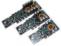
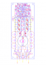
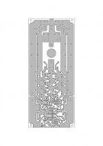
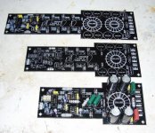
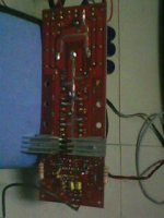
In the original datasheet there is only one pair of transistors. How can I wire 4 pairs of transistors like in this picture.
In the original datasheet there is only one pair of transistors. How can I wire 4 pairs of transistors like in this picture.
Attachments
Last edited:
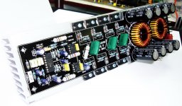
the layout looks great !!!!
but for a class AB amplifier only....
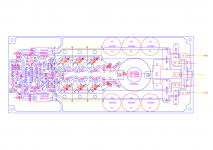
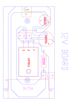
i wonder if we can see with a scope the signal on the Drain of the top MOS-FET's, close to the small 12V connector.
how many Watts they are able to deliver ???
Hmmmm I think this is class D amp. It uses IRS2092.
I would really like to hear if someone has made this.
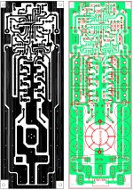
The problem is that I can't find the schematic ANYWHERE. I only dig this PCB layout. So we must build it to test it

I'll try and draw the schematic in eagle from this PCB.
Last edited:
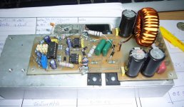
I have more info. Here is everything I could find nd IT WORKS. It is also commercial.
Attachments
-
 11(2).gif94.6 KB · Views: 899
 -
 16-12-2552 20-02-01.gif94.6 KB · Views: 813
 -
classDv1[1].pdf77.4 KB · Views: 458
-
 index.php.png105.9 KB · Views: 416
 -
 index.php1.png41.8 KB · Views: 410
 -
 index.php111.png96.9 KB · Views: 408
 -
 index.php12v.png11.4 KB · Views: 346
 -
 index.php12.png45.6 KB · Views: 380
 -
 IR-Power.jpg92.2 KB · Views: 478
 -
 irs2092d.jpg133.8 KB · Views: 451
it sure is, but what he is saying is, PCB is made for AB amps, if that
BTW, it will be waste of money, even if it will work, there is a lot more to D amps then just throw some parts together
Can you show me one that uses more than one pair of output transistors?
Use SMD (SOT-23) local buffer transistors (emitter followers) for each output MOSFET.
Although, this layout may work, parasitics make switching much slower resulting in much worse efficiency (and higher distortion) than in a proper SMD layout with 2+ layer PCB.
Parasitics will also limit the maximum rail voltage for safe operation.
3000W are possible with just four IRFB4227 when layout parasitics are low enough.
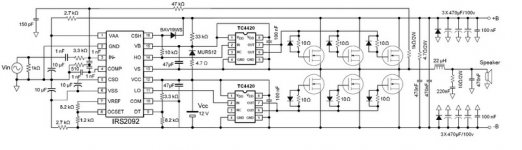
hello here is the schematic
O great man, thank you so much.
hi eva
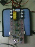
greetings can this circuit be constructed as it is with 3 output pairs
what output power would we get
thanking you
andrew lebon
In my opinion it should work really good. I am not sure if UCP700 works on the same principle or it is full bridge but the only thing I am afraid it is the PCB design. But it is not that bad.
- Status
- This old topic is closed. If you want to reopen this topic, contact a moderator using the "Report Post" button.
- Home
- Amplifiers
- Class D
- IRS2092 How to drive more then one pair of output transistors?