Tas5630 have lots of excellent functions,like 4channel/2.1 or transform driving, but Ti TAS5630EVM board haven't make it reality.
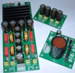
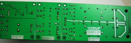
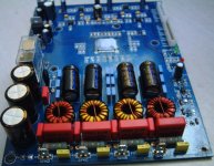
I discuss such things with Ti FAE long time ago,not get full answer.we have to try it many times to design full function boards,we finally make it three separated boards due to easy using,it can be set PBTL MODE(600W/2OHM),2BTL(2*300W/4OHM),4SE(4*145W/2OHM),2.1(2*75W+1*300W).pls give us more advice,let's make it better!
schematic here:
Attachments
Last edited:
Full Function Kits here.
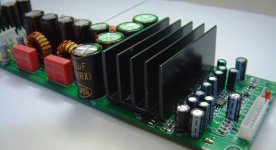
Picture here.it can deliver out 2* 250W/4ohm/2%THD+N 4hours when we burn in it,but need fan cooling.I have list some on diyaudio,http://www.diyaudio.com/forums/clas...aluminum-case-finished-new-year-coming-3.html
Picture here.it can deliver out 2* 250W/4ohm/2%THD+N 4hours when we burn in it,but need fan cooling.I have list some on diyaudio,http://www.diyaudio.com/forums/clas...aluminum-case-finished-new-year-coming-3.html
Attachments
Last edited:
Tas5630 full function kits version 2!!
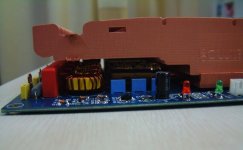
We are now debugging our lastest TAS5630FFD KITS V2,Use large cooler,we found heatsink very hot at high power (2*250W/4ohm) when used the first version board,we have to revise it and make it more stable,we have wasted lots of money on this series chip,the lastest chip TAS5613PHD excellent,little power as TAS5630PHD, but heard powerful ,use easily than TAS5630,works stable.feel better than TAS5615PHD.
I am not suggest using TAS5630 DKD,specification looks good,but not in reality.PHD good.
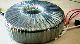
Power supply is very important,firt step add +12v ,main power later.we have to make power circuit to realize it.
The rest circuit not good in datasheet ,but this function is useful in pro amplifier development.
I test these TAS series chip from 2007.05,TI FAE forbided us let other know ,I write some experience in my blog,but was deleted by ti ,due to protection it's intellectual property。I revised later.
I have made some modules like 2*150W +smps use TAS5630(4 version now) 2*100W +smps use TAS5615(2 version now),TAS5630 FULL FUNCTION KITS,TAS5615 FULL FUNCTION KITS.
This board up write I will use it at 200W*2 or 1*400W ,SMPS have finished.
Some friends on diyaudio have our modules,thanks you support,pls give us more suggestion,we will make it better. Thanks.
We are now debugging our lastest TAS5630FFD KITS V2,Use large cooler,we found heatsink very hot at high power (2*250W/4ohm) when used the first version board,we have to revise it and make it more stable,we have wasted lots of money on this series chip,the lastest chip TAS5613PHD excellent,little power as TAS5630PHD, but heard powerful ,use easily than TAS5630,works stable.feel better than TAS5615PHD.
I am not suggest using TAS5630 DKD,specification looks good,but not in reality.PHD good.
Power supply is very important,firt step add +12v ,main power later.we have to make power circuit to realize it.
The rest circuit not good in datasheet ,but this function is useful in pro amplifier development.
I test these TAS series chip from 2007.05,TI FAE forbided us let other know ,I write some experience in my blog,but was deleted by ti ,due to protection it's intellectual property。I revised later.
I have made some modules like 2*150W +smps use TAS5630(4 version now) 2*100W +smps use TAS5615(2 version now),TAS5630 FULL FUNCTION KITS,TAS5615 FULL FUNCTION KITS.
This board up write I will use it at 200W*2 or 1*400W ,SMPS have finished.
Some friends on diyaudio have our modules,thanks you support,pls give us more suggestion,we will make it better. Thanks.
Attachments
Last edited:
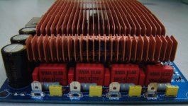
Snuber resister always cool,only warm at high frequency,above 10K frequency,I think your inductor selection wrong when no singal warmer.
I just wonder, why you needed to use such big resistors, if in the TI reference design there are some SMD 0805 resistors used

Attachments
I just wonder, why you needed to use such big resistors, if in the TI reference design there are some SMD 0805 resistors used
For my pro amp developing experiences ,so much power out and high frequency carrier wave deliver out ,snuber circuit should assume much more power dissipation on resister.1W or 2w resister should right.
Here using SMD resister only make it toy。
Ok, another question
Why the TI evaluation module has no any power-up sequnce schemes and you was needed to use a relay there? TI EVM module simply derive the +12V via stabilizer from PVDD (+50V) and seems has no any problems with it. In my prototype I do the same, and had no any burned chips... How can you explain it?
Why the TI evaluation module has no any power-up sequnce schemes and you was needed to use a relay there? TI EVM module simply derive the +12V via stabilizer from PVDD (+50V) and seems has no any problems with it. In my prototype I do the same, and had no any burned chips... How can you explain it?
Ok, another question
Why the TI evaluation module has no any power-up sequnce schemes and you was needed to use a relay there? TI EVM module simply derive the +12V via stabilizer from PVDD (+50V) and seems has no any problems with it. In my prototype I do the same, and had no any burned chips... How can you explain it?
Ti EVM use dc-dc ,I haven't use this ,due to I want make it sound more clearly(no high frequency influence),I use liner regulator ,and I always use it with SMPS,so little cost from main transformer divide +15V,then down to +12v.
you have to burn some chip when you apply sinewave singal and measure rms power,only heard large sound from speaker not mean large power out.
you have to adjust heat balance and plan current route,every paramter must be measured and try it many times,so we will make product more and more goodl and get more and more excellent products,
EVM only for reference design.not product,like our factory TAS5630 FULL FUNCTION KITS(Wholesale TAS5630 Product-TAS5630 CLASS D FULL POWER FULL FUNCTION MODULE)
our TAS5630 FULL FUNCTION KITS have all open circuit and you can try all function of TAS5630.
I had burnt 5 tas5630dkd use TI TAS5630DKD EVM in 2008 when I measured the chip parameter.
As developer burnt some chip always met,we will be victor at last.
Last edited:
I lower the gain but I have decreased the out put. I am trying the get this unit to give me a 150Db output and the only way to do this that I have came up with is the increase the input amplitude. The issue I keep running into is this chip will not take a Input signal larger than 6v rms at best and only for a short time. Anyone out there with any Idea how to get past this issue?
I lower the gain but I have decreased the out put. I am trying the get this unit to give me a 150Db output and the only way to do this that I have came up with is the increase the input amplitude. The issue I keep running into is this chip will not take a Input signal larger than 6v rms at best and only for a short time. Anyone out there with any Idea how to get past this issue?
Tas5630 max input voltage is -0.3-5V,I think if you input signal above this it will dead,you can divided it .
Attachments
I thought the gain of the amp was 23dB? Shouldn't an input voltage of 1.77Vrms give an output of 25Vrms?
I can't unstand it,get 25Vrms easily,when you input about 1.8Vrms,output will out 25v,power supply voltage is 50v.
One important part I left out, I am running a 2 OHM load.
also easy,use PBTL mode at 2ohm,only 312w@25V,try it yourself!
- Status
- This old topic is closed. If you want to reopen this topic, contact a moderator using the "Report Post" button.
- Home
- Amplifiers
- Class D
- How can we make tas5630 as full function amp?