no you will have to put your ear 10cm close to the speakers to hear it. no worries, it will never be noticed.
Do the meanwell power supplies hum aswell . Is the huming through the speakers as i would not beable to live with it if i heard a hum on quiet bits in the music
for my T2, i bought the connexelectronic 38V smps300r from hifimediy. it's a bit more than the meanwell, but it's small to put in tight fitting case and runs real cool. ZERO hum even with just rough wiring (ie, no case etc, just a test setup). 28V costs the same as the 38V version. i'd recommend going for the max voltage suited to your board (around 34-35V, which the 38V one can be adjusted to).
just my opinion, i'd say you get what you pay for, you won't need to add any caps or worry about signal noise. worth paying the extra compared to the ebay one.
Power supplies
just my opinion, i'd say you get what you pay for, you won't need to add any caps or worry about signal noise. worth paying the extra compared to the ebay one.
Power supplies
+1for my T2, i bought the connexelectronic 38V smps300r from hifimediy. it's a bit more than the meanwell, but it's small to put in tight fitting case and runs real cool. ZERO hum even with just rough wiring (ie, no case etc, just a test setup). 28V costs the same as the 38V version. i'd recommend going for the max voltage suited to your board (around 34-35V, which the 38V one can be adjusted to).
just my opinion, i'd say you get what you pay for, you won't need to add any caps or worry about signal noise. worth paying the extra compared to the ebay one.
Power supplies
")
Rod,
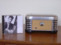
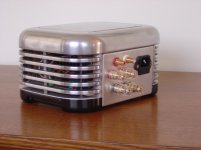
Amp and power supply cased in a hot plate/toaster oven manufactured around 1937. It was called a caulkins breakfaster. Cast aluminum required a lot of elbow grease to make it look good.
boone
This is one of the best I've ever seen !!!!!
+2
T2 Special + connexelectronics power supply - very compact!
I want one!
Hey, is there any chance I could save my Hifimediy AMT 2050 V1.2?
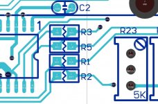
I desoldered R1 and R3 inpu tresistors(?) to increase the gain. Yes, I should have read hifimediys post which told me to change R2 and R3 and not touch R1 at all. The problem is now that the thin connection under the surface of the PCB going from R3 towards TC2000 is cut and with my solder skills i am not able to solder it back on. The original value of all R1, R2, R3 and R5 are 22k ohm and I liked the gain value when my resistors values were R1 22k, R2 56k, R3 56k, R5 22k.
If i remember correct those resistor pairs(R1,R3 and R2,R5) were in parallel/series. So my question is is it possible to let R3 be unconnected and change R1 to a value that matches with R2 being 56k and R5 22k?
Another question, does it damage the amplifier when my R3 was unconnected and the amp was on. The channel voltage showed 29.4V :/
This was another lesson for me not do things in a hurry. Always something goes wrong.
Last edited:
Hey, is there any chance I could save my Hifimediy AMT 2050 V1.2?
I desoldered R1 and R3 inpu tresistors(?) to increase the gain. Yes, I should have read hifimediys post which told me to change R2 and R3 and not touch R1 at all. The problem is now that the thin connection under the surface of the PCB going from R3 towards TC2000 is cut and with my solder skills i am not able to solder it back on. The original value of all R1, R2, R3 and R5 are 22k ohm and I liked the gain value when my resistors values were R1 22k, R2 56k, R3 56k, R5 22k.
If i remember correct those resistor pairs(R1,R3 and R2,R5) were in parallel/series. So my question is is it possible to let R3 be unconnected and change R1 to a value that matches with R2 being 56k and R5 22k?
Another question, does it damage the amplifier when my R3 was unconnected and the amp was on. The channel voltage showed 29.4V :/
This was another lesson for me not do things in a hurry. Always something goes wrong.
Hi, I don't think un-connect R3 is ok, but your amp may not be damaged if just R3 disconnected. You can see from sch that R3 is a feedback resistor so it's quite normal to output high voltage when you open the feedback loop.
I will post a picture here below, may help you to repair.
Attachments
Ok I'll have to try to repair it. Luckily i have two of those amps so got the other soldered properly. But what i noticed that, there is quite alot more "hiss" compared to the V2.0 version, is this normal? I swapped R3 and R2 to 56k ohm resistors. In my V2.0-board the equivalent resistors were 47k, if that affects?Hi, I don't think un-connect R3 is ok, but your amp may not be damaged if just R3 disconnected. You can see from sch that R3 is a feedback resistor so it's quite normal to output high voltage when you open the feedback loop.
I will post a picture here below, may help you to repair.
My powersource is a 36V lithium ion if that matters. It should produce noiceless power iv'e understood correct.Ok I'll have to try to repair it. Luckily i have two of those amps so got the other soldered properly. But what i noticed that, there is quite alot more "hiss" compared to the V2.0 version, is this normal? I swapped R3 and R2 to 56k ohm resistors. In my V2.0-board the equivalent resistors were 47k, if that affects?
Ok I'll have to try to repair it. Luckily i have two of those amps so got the other soldered properly. But what i noticed that, there is quite alot more "hiss" compared to the V2.0 version, is this normal? I swapped R3 and R2 to 56k ohm resistors. In my V2.0-board the equivalent resistors were 47k, if that affects?
I think it's not normal. You can try again when you fixed it. And try to check the input connector/cable when you still have such problem.
I am looking into building my second amplifier to drive my LR front and centre speakers in my home threater system. I built a HiFiMediy T4 a few months ago and was thinking about using the same amplifier with the SMPS500R in the new build. This leads to my question: Can you drive 2 T4s from 1 SMPS500R?
I ordered a T2 a while back, and it's been waiting in its shipping box since; I also got a T1-M which is wonderful at keeping me busy
Now that I hooked the T2 up to a 24V (2x12V SLA) battery (25.4V measured voltage) and two 4 ohm car speakers, there are several problems:
I notified hifimediy of the problem by replying to my invoice, but haven't yet heard anything from them.
Does anyone have any ideas as to what could be wrong?
Now that I hooked the T2 up to a 24V (2x12V SLA) battery (25.4V measured voltage) and two 4 ohm car speakers, there are several problems:
- The output is very noisy, worst at zero volume
- The output is very distorted
- There seem to be PWM artifacts present (certain "buzziness" in the sound)
I notified hifimediy of the problem by replying to my invoice, but haven't yet heard anything from them.
Does anyone have any ideas as to what could be wrong?
Hi there
I would like to use ane iPhone as audio source for the t2. As far as I know there will be a problem with the input sensitivity on the t2. Could anyone please advice me which resistors should be swapped? What would be the rating of the new resistors? Does anyone know the output sensiticvity of an iphone? Lots of qustions ;-)
Thanks in advance
Cheers
After some looking for a TK2050 amplifier I really don't know which one to buy.
Which amplifier and PSU is recommended for speakers with the following specs?
Element: 1" SuperAudio-treble, 2 x 3,5-" base
Impedance: 6 Ohm
Freq.range: 50-32000 Hz, 100-24000 Hz (+-6 dB), 150-22000 Hz (+-3 dB)
Delningsfrekvens: 4200 Hz
Sensitivity: 88 db (-+3 dB)
Max Power: 110 W
R.M.S. Power: 55 W
Thanks!
Just ordered a tk2050 board to play around with and couple of 500W switch mode power supplies.
I am only up to page 3 in this thread but, I want to ask a question.
I am thinking of parralleling left and right channel into one channel. Is there any significant issues with doing that?
I am a class D dumb head.
I am only up to page 3 in this thread but, I want to ask a question.
I am thinking of parralleling left and right channel into one channel. Is there any significant issues with doing that?
I am a class D dumb head.
Just ordered a tk2050 board to play around with and couple of 500W switch mode power supplies.
I am only up to page 3 in this thread but, I want to ask a question.
I am thinking of parralleling left and right channel into one channel. Is there any significant issues with doing that?
I am a class D dumb head.
You can not parallel outputs in these amps. You can use T3 ot T4 instead if you need more power.
- Status
- This old topic is closed. If you want to reopen this topic, contact a moderator using the "Report Post" button.
- Home
- Amplifiers
- Class D
- New TK2050 board