Update on the boards
Hi everyone, an update on the boards:
Jean-Paul, who was one of the lucky two that got one of the first boards I sent out some weeks ago, pointed out to me yesterday that one resistor gets quite warm, and its a bit close to some 100uf caps. We discoverd that this is because the board is using 12V relays, and this resistor is dropping the voltage so it is acceptable for the 12V relays. Jean-Paul proposed that it would be better to use 24V relays which would need a smaller voltage drop by this resistor, hence less heat. I discussed this with hifimediy, and he pointed out that the 24V relays would give a smaller input voltage range. But anyway we decided to go for 24V relays. He had already some boards finished, but said it would only be 2-3 days delays if changing to the 24V relays, so I thought most people would think it is worth waiting another 3 days to get a less hot resistor.")
The new input voltage range will be in the range of 24-33VDC, have to confirm this with hifimediy when he knows the exact specs for the 24V relays.
If you want or need to use higher or lower voltages you can simple change this one resistor (R36) to another value. I can supply more information on this when its confirmed.
So, this means i will have the first boards in about 3 days. Sorry for the extra delay, but as it was only 3 days in question, and as the result might be better, I thought everyone would be happy to wait.
Thanks to jean-paul for pointing this out.
Regards,
Steinar
Hi everyone, an update on the boards:
Jean-Paul, who was one of the lucky two that got one of the first boards I sent out some weeks ago, pointed out to me yesterday that one resistor gets quite warm, and its a bit close to some 100uf caps. We discoverd that this is because the board is using 12V relays, and this resistor is dropping the voltage so it is acceptable for the 12V relays. Jean-Paul proposed that it would be better to use 24V relays which would need a smaller voltage drop by this resistor, hence less heat. I discussed this with hifimediy, and he pointed out that the 24V relays would give a smaller input voltage range. But anyway we decided to go for 24V relays. He had already some boards finished, but said it would only be 2-3 days delays if changing to the 24V relays, so I thought most people would think it is worth waiting another 3 days to get a less hot resistor.
The new input voltage range will be in the range of 24-33VDC, have to confirm this with hifimediy when he knows the exact specs for the 24V relays.
If you want or need to use higher or lower voltages you can simple change this one resistor (R36) to another value. I can supply more information on this when its confirmed.
So, this means i will have the first boards in about 3 days. Sorry for the extra delay, but as it was only 3 days in question, and as the result might be better, I thought everyone would be happy to wait.
Thanks to jean-paul for pointing this out.
Regards,
Steinar
Anyone knows anything about this baby:
eBay.be: 2*100w 4? TK2050 Class-D Audio Amplifier Board-improved (objet 380233022408 Fin: 19-mai-10 20:23:28 CEST)
eBay.be: 2*100w 4? TK2050 Class-D Audio Amplifier Board-improved (objet 380233022408 Fin: 19-mai-10 20:23:28 CEST)
Last edited:
Kidding?
You are kidding right?
.
http://www.diyaudio.com/forums/class-d/143669-sure-electronics-new-tripath-board-tc2000-tp2050.html
.
Anyone knows anything about this baby:
eBay.be: 2*100w 4? TK2050 Class-D Audio Amplifier Board-improved (objet 380233022408 Fin: 19-mai-10 20:23:28 CEST)
You are kidding right?
.
http://www.diyaudio.com/forums/class-d/143669-sure-electronics-new-tripath-board-tc2000-tp2050.html
.
Why not put 2 12v relays in series? That way you will have less voltage to drop, but the same amperage.
Hifimediy mentioned that solution first.
Would it be as stable as having 24V relays in parallel?
It might actually be more stable, as the 12v relays might even switch at 8v, meaning 16v is enough.
It requires just as much current through the resistor as a single 12v relay, but the required voltage drop is less than half, thus less heat.
It might even save you a diode, as they both can be on the same diode
It requires just as much current through the resistor as a single 12v relay, but the required voltage drop is less than half, thus less heat.
It might even save you a diode, as they both can be on the same diode
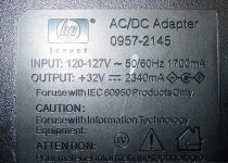
HP smps +32V
Based on the anecdotes of the big sure tk2050 thread, I've found an inexpensive HP SMPS to power this board. Is this thing feasible?
Do I need + and - 32V, or is +32V enough?
Forgive my noobish question.
I am excited to play with this board.
Based on the anecdotes of the big sure tk2050 thread, I've found an inexpensive HP SMPS to power this board. Is this thing feasible?
Do I need + and - 32V, or is +32V enough?
Forgive my noobish question.
I am excited to play with this board.
Attachments
I use this one... It works great and I got it for $12...Good Luck..
HP A/C POWER ADAPTER D135 D145 7110 7130 C7296-60024 - eBay (item 330351604514 end time Jun-07-10 11:55:58 PDT)
HP A/C POWER ADAPTER D135 D145 7110 7130 C7296-60024 - eBay (item 330351604514 end time Jun-07-10 11:55:58 PDT)
Why not put 2 12v relays in series? That way you will have less voltage to drop, but the same amperage.
hi, I just test new boards with 24V relay, and it works good. resistor cool down now.
and 2x 12V relay in series is ok too. not much difference from 24V in parallel i think.
I use this one... It works great and I got it for $12...Good Luck..
HP A/C POWER ADAPTER D135 D145 7110 7130 C7296-60024 - eBay (item 330351604514 end time Jun-07-10 11:55:58 PDT)
Nice. 3 amps is better than 2.4

Thanks.
teamacc said:Just + will do, no need for negative voltage
The psu looks a little undersized, you might wanna upgrade to more amperes, but some beefy buffer caps might do the job just as well.
Thanks!
Last edited:
Hi, I'm planing the new 50W+50W amp now, this is new design.

V1.1B has the same board size and potmeter location as AMT2050 V2.0, but it's DC input only. For V1.1B, a switch and a relay are added to switch power, the swith system is designed to prevent power input polarity reverse, this design will be better than just using a diode.
Could anyone give me some suggestion to improve?
hifimediy

Hi, I'm planing the new 50W+50W amp now, this is new design.
V1.1B has the same board size and potmeter location as AMT2050 V2.0, but it's DC input only. For V1.1B, a switch and a relay are added to switch power, the swith system is designed to prevent power input polarity reverse, this design will be better than just using a diode.
Could anyone give me some suggestion to improve?
hifimediy
Hi hifimediy, i would leave more space between the right output coil and the input caps. Also distance between electrolytic caps C33/C37 and the heatsink is too small. Hot caps die soon. The tank cap is quite small with 1800 uF, make that a 2200/3300/4700 uf with at least 2 mm space between it and the heatsink. I hope the tank cap is always under voltage as when you will switch it with the relay the relays contacts will burn in quite soon. You could use 2 smaller caps. So 1800 uF before the relay and one 1800 after the relay.
Swap CN2 and relays K3 as it will be a more logical layout then. Don't change anything that might look better but is worse technically in your opinion !
Moving all LEDs to one spot will be more logical. A connector in the upper right corner or even better in the lower left corner would be more tidy. The lower left corner is more logical as one tends to mount LEDs on a front panel. You can connect a small cable harness to the 2 LEDs that will be mounted on the front panel. LEDs that are not visible have no function
If the layout would suffer please keep it like it is now as sound quality is much more important than LEDs.Connector J1 is also placed not optimal. Please move it over to the spot where the text "AMT2050 " is. And move that text to the spot where J1 was and it will be OK. Wiring should be kept as short as possible. It makes no sense to me to put the connector near the front panel. Wiring will be longer for no reason and it will look messy, can pick up garbage if unshielded wire is used etc. The connector is also too close to the mounting stud + bolt which will make it more easy to damage it.
This should be a version 2.1 or like wise if it has the same name "AMT2050" as it is newer than the old one. Again I think that offering a version with 4 or 5 inputs and a Alps RK27 would be a unique version as all manufacturers offer amps with only one input. When you add pads for the RK27 you can leave the choice to the buyer. Either the cheaper one that is offered now or a small upgrade to RK27.
Last edited:
if someone want to change relay connection to in series, please follow these steps:
1. remove diode D12 (hole mounted 1N4007) and the relay near it.
2. cut off two tracks and short 2 holes show in the photo.
3. assemble the diode and relay. done.

Methinks the resistor should be lower in value when the relays are connected in series.
Since STA517B now is available, why not design a board with it, like 41hz amp11-hv does, that will be a huge hit here, I believe
hi, it's another product (larger boards needed) i think, and i will consider it next time. Good suggestion, thanks.
Hi hifimediy, i would leave more space between the right output coil and the input caps. Also distance between electrolytic caps C33/C37 and the heatsink is too small. Hot caps die soon. The tank cap is quite small with 1800 uF, make that a 2200/3300/4700 uf with at least 2 mm space between it and the heatsink. I hope the tank cap is always under voltage as when you will switch it with the relay the relays contacts will burn in quite soon. You could use 2 smaller caps. So 1800 uF before the relay and one 1800 after the relay.
Swap CN2 and relays K3 as it will be a more logical layout then. Don't change anything that might look better but is worse technically in your opinion !
Moving all LEDs to one spot will be more logical. A connector in the upper right corner or even better in the lower left corner would be more tidy. The lower left corner is more logical as one tends to mount LEDs on a front panel. You can connect a small cable harness to the 2 LEDs that will be mounted on the front panel. LEDs that are not visible have no function
Connector J1 is also placed not optimal. Please move it over to the spot where the text "AMT2050 " is. And move that text to the spot where J1 was and it will be OK. Wiring should be kept as short as possible. It makes no sense to me to put the connector near the front panel. Wiring will be longer for no reason and it will look messy, can pick up garbage if unshielded wire is used etc. The connector is also too close to the mounting stud + bolt which will make it more easy to damage it.
This should be a version 2.1 or like wise if it has the same name "AMT2050" as it is newer than the old one. Again I think that offering a version with 4 or 5 inputs and a Alps RK27 would be a unique version as all manufacturers offer amps with only one input. When you add pads for the RK27 you can leave the choice to the buyer. Either the cheaper one that is offered now or a small upgrade to RK27.
Hi, jean-paul. thank for your suggestions.
This is a DC supply board and i have to prevent polarity reverse, that's why i don't put elec-caps before the relay. May be it's better to add a PSU board for best use.
About CN2 and K3, they seem very logical for layout now and i will show the layout behind. so it's ok i think.
For LEDs, i place a protection LED near the right uper coner to prevent long distance route. I think it's better to use wire to mount it on the front panel if necessary.
And for J1, same reason for place it near the pot, the track will be shortest. it's also keep same as V2.0 does.
I have to explain how V1.1B comes.
For this version, it's not paralleled, so it will be V1.x, and i already have V1.0 before. V2.x means paralleled power stage boards(there is just V2.0 now).I will consider all of your advice and do changes when it's needed, and I also may take some of them for my other products.
thanks again.- Status
- This old topic is closed. If you want to reopen this topic, contact a moderator using the "Report Post" button.
- Home
- Amplifiers
- Class D
- New TK2050 board