nice !!!
Hi
I would like to congratulate you for your amp. Looks lovely.
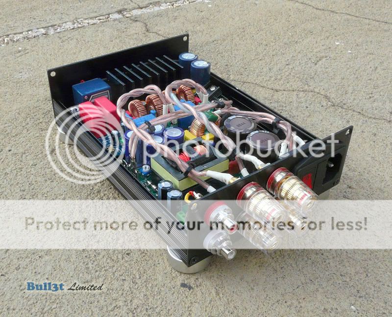
But i have some suggestions . If i were you i would move the amp board on the back side of the chassis & the power pcb on the front. By this way you will limit the length of the signal cables. You have tighten the left channel output cable with the AC input cables. This is not good, you might get noise coming from the AC line there. If it is not possible to do it (probably because of the limitations of your box) use a different route for the left channel output cable. Overall that is a very nice amp. I have the same one & just changed the input capacitors with better ones as you have already done with those wima mkp4 there (it is better to use wima mkp10 here) . .
.
Hi
I would like to congratulate you for your amp. Looks lovely.
But i have some suggestions . If i were you i would move the amp board on the back side of the chassis & the power pcb on the front. By this way you will limit the length of the signal cables. You have tighten the left channel output cable with the AC input cables. This is not good, you might get noise coming from the AC line there. If it is not possible to do it (probably because of the limitations of your box) use a different route for the left channel output cable. Overall that is a very nice amp. I have the same one & just changed the input capacitors with better ones as you have already done with those wima mkp4 there (it is better to use wima mkp10 here) .
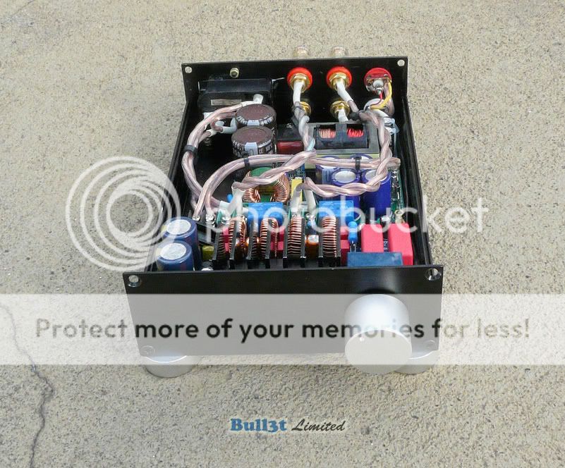
.Ok, here goes my finished T1 Alps STA510A v1.2 + Connexeletronics SMPS300R
An externally hosted image should be here but it was not working when we last tested it.
Last edited:
Hi
I would like to congratulate you for your amp. Looks lovely.
But i have some suggestions . If i were you i would move the amp board on the back side of the chassis & the power pcb on the front. By this way you will limit the length of the signal cables. You have tighten the left channel output cable with the AC input cables. This is not good, you might get noise coming from the AC line there. If it is not possible to do it (probably because of the limitations of your box) use a different route for the left channel output cable. Overall that is a very nice amp. I have the same one & just changed the input capacitors with better ones as you have already done with those wima mkp4 there (it is better to use wima mkp10 here) .
Ok, here goes my finished T1 Alps STA510A v1.2 + Connexeletronics SMPS300R

I can route the left speaker in between PSU capacitors in the midle but them it will be closer to the PSU and its transformer, I don't know wich is worse but I haven't got any kind of noise or humm as it is now.
boom!
My T1 board was not unmuting this morning so I have opened the case to discover that (chip cooler has been removed for the pictures):
C32 has blown, PCB traces are damaged beyond repair and PCB itself is deeply burned.
The cap is 16 V, not sure it is adapted due to it's position:
This ampli has not been pushed too hard as it is driving diy loudspeakers limited to 20W (8 ohms). It remains powered very often as I usually forgot to switch it off when the music end...
I have mailed Steinar to know if a repair or an exchange is possible. After having suffer from blown caps on V2 and sticky relay on this one, I almost ready to stop the experience...
My T1 board was not unmuting this morning so I have opened the case to discover that (chip cooler has been removed for the pictures):
An externally hosted image should be here but it was not working when we last tested it.
An externally hosted image should be here but it was not working when we last tested it.
An externally hosted image should be here but it was not working when we last tested it.
C32 has blown, PCB traces are damaged beyond repair and PCB itself is deeply burned.
The cap is 16 V, not sure it is adapted due to it's position:
An externally hosted image should be here but it was not working when we last tested it.
This ampli has not been pushed too hard as it is driving diy loudspeakers limited to 20W (8 ohms). It remains powered very often as I usually forgot to switch it off when the music end...
I have mailed Steinar to know if a repair or an exchange is possible. After having suffer from blown caps on V2 and sticky relay on this one, I almost ready to stop the experience...
Images were not clickable:
An externally hosted image should be here but it was not working when we last tested it.
An externally hosted image should be here but it was not working when we last tested it.
An externally hosted image should be here but it was not working when we last tested it.
An externally hosted image should be here but it was not working when we last tested it.
My T1 board was not unmuting this morning so I have opened the case to discover that (chip cooler has been removed for the pictures):
Did Hifimediy or Steinar not reply to your problem via eMail/PM ?
I haven't found any 270uf with higher specs, can I change it for a 330uf 35V? Or maybe change C34 also to keep the same capacitance?
is it better to go for a larger or smaller value since max current are supposed to be at 120mA?
anyone?
for anyone else that's interested and gets email updates to this thread, the Hifimediy T2 special version 2*100W@4ohm/50W@8ohm amplifier STA510a (Nichicon KG 10000uf) with MUNDORF MCAP input caps is back in stock!! others have said it's a great sounding piece of kit, but i can't comment yet having only just ordered it.
I haven't found any 270uf with higher specs, can I change it for a 330uf 35V? Or maybe change C34 also to keep the same capacitance?
is it better to go for a larger or smaller value since max current are supposed to be at 120mA?
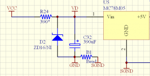
Hi, I think 220uF~680uF is ok here.
I also suggest using the sch bellow as we do on new T1.
R24 can be a 270~390ohm 1Watt resistor and C32 has range from 220~680uF, and no less than 35V. D2 is not installed.
Attachments
Last edited:
I've got a T2 Special board using 2x STA510 and have a doubt about it.
a single STA505 is capable of delivering araound 2x 50W Full Bridge.
a single STA510A is capable of delivering around 2x 100W Full bridge as seen on T1 1.2
Normal T2 board comes w/ 2x STA505 single bridge paralled, so it's capable of delivering around 2x 100W RMS
So why T2 Special delivers the same power as the normal one using STA505?
If it's using 2x STA510A paralled single bridge it should deliver around 180W each channel at 4Ohms, so why it's only rated 2x 100W? It isn't using a single bridge configuration for each chip? Where are the other 2 channels dead?
Hi, when use same power supply and load, the T2(sta510A) will output same power as T2(sta505). So, T2(sta510A) only relives higher power when higher supply voltage or/and lower impedance load.
[*]A PGA2311 pre-amp module with LCD display (eBay), 3 inputs and remote control. I really like this preamp module wich is dead quiet
Maarten,
Which module is this? Can you share please.
At the moment there are at least 20 kits/assembled boards offered on Ebay, most are the same board sold as kits or assembled by different vendors and sometimes with different components or firmware. Please search on pg2311 and skip the IC's and look for the boards. The latest version has a memory function which remembers the last input/volume setting after a power off/on cycle.
Example of PGA2311 board with memory function
RqqTywQ~~60_12.JPG)
Maarten
Example of PGA2311 board with memory function
Maarten
Last edited:
@Maarten,
I know these PGA2311 boards. Fine solution with this type of controllers. The problem I see here is to cut a matching frame into a chassis. Or are these standard dimensions ... ? Would be glad if you success with an implementation and demonstrate us here.
See post 2031 of this thread. The case was made of steel and indeed cost me a lot of trouble to cut the hole for the display. The display sticks through the hole in this case. Maybe next time I would have made the hole a little smaller and have the display attached behind the front plate.
This should be a lot easier when using aluminum boxes, especially when cutting a slightly smaller hole than the display. Only when the frontplate is 10mm thick this will again be tricky. Some sellers will make such holes on request and I'm seriously considering going that route for one of my next projects.
BTW on ebay there are "standard" chassis available for this board.
regards,
Maarten
BTW on ebay there are "standard" chassis available for this board.
regards,
Maarten
I think I have also seen these. They were silver colored if I am not wrong. But you can use them only as a pre-amp chassis and it should nearly impossible to integrate a bigger powersupply and the Tripath pcb in same chassis.
sorry, I just have said that I know/read about them. Sadly I cannot give any experiencesMaarten, TheDealer,
How transparent are these pre-amps? What type of coloration do you hear them adding?
-Zia
Maarten, TheDealer,
How transparent are these pre-amps? What type of coloration do you hear them adding?
-Zia
as transparent as a resistor
As long as you use pga2310/11 below 0dB, it's a passive attenuator.
From 0 to +36dB there is an opamp included, based on opa2134. It is quite good, but you may or not like. I don't care as I use it only as passive. Modern dacs don't need preamp gain.
These boards have a dc blocking cap. I simply bypassed them.
- Status
- This old topic is closed. If you want to reopen this topic, contact a moderator using the "Report Post" button.
- Home
- Amplifiers
- Class D
- New TK2050 board