Hello.
This schematic is a car amplifier, and i wish to change with your help!
Rail +/- 116v, and clipping start at ~73Vrms of output (without loud)
I suppose that clipping is introduced by preamplifier section.
Please help me with some ideas , what minor changes I need to do to eliminate that clipping!
This schematic is a car amplifier, and i wish to change with your help!
Rail +/- 116v, and clipping start at ~73Vrms of output (without loud)
I suppose that clipping is introduced by preamplifier section.
Please help me with some ideas , what minor changes I need to do to eliminate that clipping!
Attachments
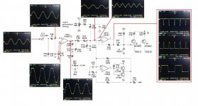
If it's clipping at 73V RMS, that means it has peaks that are 73*SQRT(2) = 103 volts. With a class D amp there's only so far you can get the duty cycle, so it's not really that far off.
However, looking at your schematic and measurements has me thinking there's something wrong with your setup. There's 4.68 Vrms on the input, but 5.33 Vrms on the non-inverting leg of the op-amp. Considering the signal is at around 50Hz and looking quite dirty, I'm wondering if what you're measuring isn't bad grounding of the oscilloscope probe.
However, looking at your schematic and measurements has me thinking there's something wrong with your setup. There's 4.68 Vrms on the input, but 5.33 Vrms on the non-inverting leg of the op-amp. Considering the signal is at around 50Hz and looking quite dirty, I'm wondering if what you're measuring isn't bad grounding of the oscilloscope probe.
Hello.
This schematic is a car amplifier, and i wish to change with your help!
Rail +/- 116v, and clipping start at ~73Vrms of output (without loud)
I suppose that clipping is introduced by preamplifier section.
Please help me with some ideas , what minor changes I need to do to eliminate that clipping!
I suppose you use the input signal of about 10-15 KHZ, right? and if your output filter has too much inductance and too high capacitance, then it's cutoff frquency will be at this frequency already and you will newer get full rail to rail output swing at this frequency... Check it at 1KHZ instead, or at 100HZ at all...
")
P.S.: oh sorry, I see now, it is 50HZ...
then I have no idea
Last edited:
You may not like the result if the output stage of the amplifier is allowed to clip. Clicks, sticking to the rails, and oscillations may be the result. In many class D circuits the modulator is intentionally made to clip before the output stage, or the signal is pre-clipped according to instantaneous supply voltage.
I change R57 + R37 with a smaller resistor.
I removed R57 (short circuited it) and the clipping threshold moved to 75V.
Is modifying the values of the resistors a good solution ?
You have got the answer in second post in this topic already from user runebivrin: with +/-116 rail voltage you newer get 116 RMS voltage at output! With +/-116V rail voltage theoretical limit is 116/sqrt(2) ~= 116/1.414 ~= 82Vrms. And practically class D amp has a limit in minimal pulse width and has Rdson resistance of output mosfets, which limits the maximal output swing. To understand the things better, switch your oscilloscope to show you the Vpp (peak to peak) instead of Vrms, and connect it to the OUTPUT of your amp
I would not modify any resistors in this amp to get another additional 8-9 volts at output, otherwise probably you will end with die amp.
Last edited:
- Status
- This old topic is closed. If you want to reopen this topic, contact a moderator using the "Report Post" button.
- Home
- Amplifiers
- Class D
- Class d - Clipping - Help