hi jash
have your problem ( burning resister ) rectified by adding 1uf capacitor
Not yet tested since nowdays I am busy in some other PA amplifiers for my customers. I will post the results when I will test it.
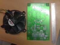
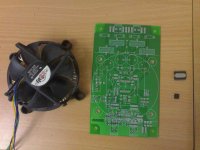
I have got a number of emails regarding PCB details. So here are the details.
In my new prototype (using a SMPS), I am supplying a seperate supply for 12 v operation. This works even better upto 49 volts.
In my new prototype (using a SMPS), I am supplying a seperate supply for 12 v operation. This works even better upto 49 volts.
Attachments
Last edited:
81bas
mmmmm.
I just knew why you commenting on my topic, You also do the same on other users topics, so this is normal.
It looks we Have anothe (EVA) on the forum
But belive me one (EVA) is just fine.
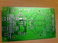
You have no parallel ceramic caps for two electrolythics in your design... and it is a big mistake not to use a input 100pf ceramic caps at the inputs as shown in the reference design...
Also, seems you have used a 7812 stabilizer here, but most of them have overvoltage protection at about 35-40 volts. And it is not a good idea to power output mosfets without powering their driver...
mmmmm.
I just knew why you commenting on my topic, You also do the same on other users topics, so this is normal.
It looks we Have anothe (EVA) on the forum
But belive me one (EVA) is just fine.
Good
Nice Work Man...
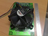
Sorry here is my attachment..... And i am using CPU processor heatsink
Nice Work Man...
what about the RC snubber, it is working ?
yes, it works. I will incorporate it in my new PCB design
yes, it works. I will incorporate it in my new PCB design
What was the reason that it had burned previously?
hi guys ,
i have got a tas 5630 phd .I have no technical knowledge except that i can solder very well and i need help in getting pcb design for the amplifire+power supply .Please help
Every thing is in the thread. see post # 23.
Further, if you dont have enough technical knowledge of class D's, dont even think of making this amp because it requires much skill and knowledge to make it working (rather, sound it) otherwise you will only mess up with a lot of oscillations and burnt chips
 .
.If anything is wrong in design, the chip simply keeps its circuitry dead and you will be unable to hear any thing.
I can also make PCB for you if you like the design.
send me email - akjain2007@dataone.in
Thanks.
Gaurav
Last edited:
If anything is wrong in design, the chip simply keeps its circuitry dead and you will be unable to hear any thing.
I can also make PCB for you if you like the design.
send me email - akjain2007@dataone.in
Thanks.
Gaurav[/QUOTE]
Well not so untechnical even , But its been a lot of time, i did this stuff during college days.
And reg pcb i surely would like to get the pcb if you can share with me.
another thing , While comparing the sound quality of 5630 which other amp are you using or have used, and what would be the difference between 5630 and lm 3886 only audio perfomance wise.
And which speakers you are using for these.
If anything is wrong in design, the chip simply keeps its circuitry dead and you will be unable to hear any thing.
I can also make PCB for you if you like the design.
send me email - akjain2007@dataone.in
Thanks.
Gaurav
Firstly, I have shared the maximum that I could. Since I am selling these TAS5630 amps to many local customers. If you are intrested in PCB, I can sell it to you too
.Comparing sound quality, I didnt found much difference in low frequencies but as stated in the datasheets, THD of 5630 is poorer than LM 3886. further a minute noise is also observed in 5630. Although if you compare the power output, 5630 is better in all respect.
I am having various drivers like 2 pairs of pioneer champion series 12" TS-W1208D2, NX audio 12" PS1260 and a 15" NX audio (dont remember model).
my design......
Good chip, yet I never understood why the official EVM
uses a custom heatsink rather than standard PC style?
Would it have hurt anything to add the extra holes and
keep the tall parts out of the standard area? I like how
you have done that, but the added fan might be overkill.
I'm sure there is always good reason? But I rarely hear
the thought process at work going into these designs,
only measure the final result when testing is required...
When I get home I just want to play with my old tubes.
I get my fill of Class-D at work. On the other hand, this
EVM did sound very good in the lab. Direct side by side
with my 17WPC Fisher x100 that had just been freshend
up with new JJ's.
OK, maybe its not a fair comparison Wattwise? But
sometimes you get crazy and just want to compare
old tech vs new. Some of the new are surprisingly
good.
I've never experienced this EVM heatsink to get warm
to the touch even without a fan. Fisher's EL84-M's
(originally 7189) would take your skin off right pronto...
I've not had any probs runnning spec sheet voltages.
But I'll mention your troubles to the relevant engineer
if I can find out who that might be? I'm pretty low on
the totem, so I may or may not be allowed to bug an
engineer over something DIY we didn't build for him.
Last edited:
Actually, I've seen EVMs with up to three of this package
style side by side. So maybe this explains why the custom
heatsink rather than standard PC style? Extrude to cover
however many devices they want??? Totally guessing...
If its not in the test procedure, I'm probably the wrong
one to ask... I can't reveal the test procedure, so there
probably no point asking me anything anyhow. If its on
the public webpage and got a spec sheet, I can brag on
the good stuff. But you can read all that anyways...
Last edited:
I too am going to build with this IC. Perhaps I should buy a couple of boards; how much would that be?
I have the TI data sheet and will have to build the inductors as well as the main power supply. Contrary to common sense, I plan to make an old fashioned transformer-rectifier supply to reduce the amount of new technology, in hopes of keeping it manageable. I will need 50 Volts at maybe 15 Amperes, enough for a welding outfit, and the 12 Volt source will be trivial by comparison.
I have the TI data sheet and will have to build the inductors as well as the main power supply. Contrary to common sense, I plan to make an old fashioned transformer-rectifier supply to reduce the amount of new technology, in hopes of keeping it manageable. I will need 50 Volts at maybe 15 Amperes, enough for a welding outfit, and the 12 Volt source will be trivial by comparison.
SMPS for tas5630
I have developed one simple SMPS for TAS5630 full function modules,use flyblack topic,high power out,50V/10A, only standby power comsumption higher(about 8W),but use easily,can in series or parallel,only change high frequency transformer.
Ti EVM and suggested LLC half bridge power not good choose.
I have developed one simple SMPS for TAS5630 full function modules,use flyblack topic,high power out,50V/10A, only standby power comsumption higher(about 8W),but use easily,can in series or parallel,only change high frequency transformer.
Ti EVM and suggested LLC half bridge power not good choose.
I have developed one simple SMPS for TAS5630 full function modules,use flyblack topic,high power out,50V/10A, only standby power comsumption higher(about 8W),but use easily,can in series or parallel,only change high frequency transformer.
Ti EVM and suggested LLC half bridge power not good choose.
I have paste some picture here,http://www.diyaudio.com/forums/clas...aluminum-case-finished-new-year-coming-4.html
I can also make PCB for you if you like the design.
send me email - akjain2007@dataone.in
Thanks.
Gaurav
you mean the design you posted here or do you have some other PCB which can give upto 50V
you mean the design you posted here or do you have some other PCB which can give upto 50V
Not exactly the same as posted but with very minor corrections like snubber circuit added and some 1uF caps added on suppy pins.
- Status
- This old topic is closed. If you want to reopen this topic, contact a moderator using the "Report Post" button.
- Home
- Amplifiers
- Class D
- My new working Class D TAS5630 DKD