I always insert a low value (10 ohm) resistor in series between pin 13 of the IRS20955 and the centee node of the upper and lower mosfets. Then from pin 13 to pin 9 of the IRS20957 insert a catch diode rated at 400v 25-35nsec Trr right at the IC. This will prevent destruction of the 20957 if there are some unwanted switching spikes due to "poor" layout.
The PCB trace from pin 13, through the 10 ohm and to the centre node must use thick traces (3mm) and be as straight and direct as possible.
Would not this make OCP , over current protection out of operation?
If I am correct, , 500W around 15A, and 25W dissipation caused by Rds (on),
could work with good cooler, but, what about paralleling two mosfets in half bridge ? can that work? half bridge with 4 mosfets than only 5W per mosfet. Usually mosfets can be paralleled cause positive temperature coefficient without any resistors
Sounds like a nice idea to parallel two of those. Paralelling two smaler devices instead of uing one bigger is on the on hand very nice, becasue of halving the thermal resistace to heatsink and halving the parasitic inductances, but it also complicates the layout, heatsink mounting and increases costs.
Mosfets are perfectly parallelable with independent gate resistors.
Regardning Rdson I suggest not allowing the body diodes to conduct, anoher words to ensure that current times Rdson is lower than diode drop (0.45V or so)
I think that inductor from LC filter current makes it conduct no matter what you do
what inductor to choose
LT spice simulation shows that loop gain needs to have slight peak at the edge, less THD
so my LC filter has little peak at resonance frequency , and works good for 4 and 8 ohm
I have chosen 22uH 1uF
Here are somme inductor links, please review them !!
Dont know what to choose:
very good price , but does not work at 500kHz ?
BOURNS JW MILLER|2300HT-220V-RC|HIGH CURRENT INDUCTOR, 22UH 19A | Farnell United Kingdom
this one has high self resonance , probably good choice or ?
MURATA POWER SOLUTIONS|1422311C|INDUCTOR, 22UH, 11A | Farnell United Kingdom
and this one is smd , after all I ll make smd pcb
VISHAY DALE|IHLP6767GZER220M01|INDUCTOR, 22UH, 23A, 20% | Farnell United Kingdom
Or is it better RM10 N87 ? and self made coil ?
Or micrometals?
what inductor to choose
LT spice simulation shows that loop gain needs to have slight peak at the edge, less THD
so my LC filter has little peak at resonance frequency , and works good for 4 and 8 ohm
I have chosen 22uH 1uF
Here are somme inductor links, please review them !!
Dont know what to choose:
very good price , but does not work at 500kHz ?
BOURNS JW MILLER|2300HT-220V-RC|HIGH CURRENT INDUCTOR, 22UH 19A | Farnell United Kingdom
this one has high self resonance , probably good choice or ?
MURATA POWER SOLUTIONS|1422311C|INDUCTOR, 22UH, 11A | Farnell United Kingdom
and this one is smd , after all I ll make smd pcb
VISHAY DALE|IHLP6767GZER220M01|INDUCTOR, 22UH, 23A, 20% | Farnell United Kingdom
Or is it better RM12 N87 gapped?
EPCOS|B65815E0160A087|FERRITE CORE, GAPPED, RM12, N87 | Farnell United Kingdom
Or micrometals?
what inductor to choose
Or micrometals?
Micrometals is good.
T106-2 core with a couple of meters of enammeled copper wire.
Power inductors are no good, they get very hot.
Micrometals is good.
T106-2 core with a couple of meters of enammeled copper wire.
Power inductors are no good, they get very hot.
But many people use N87 RM10, ferrite is very linear before saturation
And core shape holds all flux inside core, what is not case with toroid..
Are those links I linked power inductors?
I am afraid I cant get micrometals
")
I am afraid I cant get micrometals
You can get t106-2 on ebay.
Or if you want a few then try amidon.
You can get t106-2 on ebay.
Or if you want a few then try amidon.
Ok.
But some papers and graphs show that ferrite is better, main problem is RF interference of toroid cores to other components..
What type are used in hypex modules?
Also T130-2 vs t 106-2 ?
As you can see hypex module use ferrite core , looks like rm 10 or rm 12 gapped
http://www.hypex.nl/index.php?option=com_weblinks&view=weblink&id=14&catid=42
Last edited:
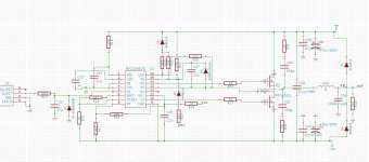
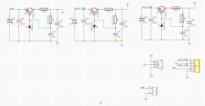
There is attached power supply and IRF20957 schematics
please check for mistakes , bad connections and orrientations..
Thanks
irf schematics is according to iraudamp7 and iraudamp4 and other irf notes
please check for mistakes , bad connections and orrientations..
Thanks
irf schematics is according to iraudamp7 and iraudamp4 and other irf notes
Attachments
Last edited:
- Status
- This old topic is closed. If you want to reopen this topic, contact a moderator using the "Report Post" button.
- Home
- Amplifiers
- Class D
- 500W amplifier using IRS20955 and IRFB4227