Has anyone given these a try? I planning on ordering a couple sure tripath boards to try a Passive Line-Level Crossover with my speakers. I've always built integrated amps before but I'm thinking a separate preamp would be good. Maybe a passive preamp would be alright, but Arjen's buffer stage is fairly cheap and runs off of 12volts so it would be easy to power. I've searched around the forum and found lots of people saying they were going to order one, but one on mentioned actually listening to one. Anybody able to offer an opinion.?
Joe
Joe
The 555 is configured as an oscillator and the output fed to a "Cockroft-Walton voltage multiplier.
See < Voltage multipliers : DIODES AND RECTIFIERS > for an explanation. I think about 8 stages are used. Does anyone know what frequency the 555 is running at?
Tony")
See < Voltage multipliers : DIODES AND RECTIFIERS > for an explanation. I think about 8 stages are used. Does anyone know what frequency the 555 is running at?
Tony
Last edited:
The 555 is configured as an oscillator and the output fed to a "Cockroft-Walton voltage multiplier.
See < Voltage multipliers : DIODES AND RECTIFIERS > for an explanation. I think about 8 stages are used. Does anyone know what frequency the 555 is running at?
Tony
i wouldn't bet on it but the Cond is a 103J100, the two resistor are 1.6 Kohm so it SHOULD work with a frequency of 30 Khz. I only see the top side of the PCB so i hope i picked the right resistors!
Just received reply from Arjen - Freq was 3kHz but on new model now increased to approx 30kHz.
After all i'm not a complete fool!
sorry guys,it cannot be 3KHz before, bcc this would be in the audio range. its not 30KHz, its in fact 40..43KHz. arjens info was just wrong by accident.
You are right, i finally saw the other side of the PCB and noticed the diode D7. Frequency should be something around 42Khz.
I noticed weird high pass filter and other solutions i don't like. If someone is interested in the complete scheme and wants to join me into modifications just let me know.
I'm talking of the original 12AU7 tube buffer, not the new MKII he has on sale now.
what high pass filter do you actually mean?
some high pass filters can work nicely in audio to prevent overloading of an amp in very low, not to hear frequencies causing distortion, especially in power amps. in arjens amp the -3dB cutoff is around 14Hz at the input filter side. this filter also disconnects cheaper devices with a DC output from the grid and also avoids "scratching" effects from a volume pot if this is not so good or heavily used.
some high pass filters can work nicely in audio to prevent overloading of an amp in very low, not to hear frequencies causing distortion, especially in power amps. in arjens amp the -3dB cutoff is around 14Hz at the input filter side. this filter also disconnects cheaper devices with a DC output from the grid and also avoids "scratching" effects from a volume pot if this is not so good or heavily used.
what high pass filter do you actually mean?
some high pass filters can work nicely in audio to prevent overloading of an amp in very low, not to hear frequencies causing distortion, especially in power amps. in arjens amp the -3dB cutoff is around 14Hz at the input filter side. this filter also disconnects cheaper devices with a DC output from the grid and also avoids "scratching" effects from a volume pot if this is not so good or heavily used.
I agree that high pass filter is needed, i'm just a lil concerned on the value/quality that has been used.
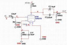
1)Input: Cap=0.33 uF , R=47Kohm. Fc=10 Hz.
this cause a phase shift of 12° at 50Hz. Isn't it better so use a bigger cap? (at least 1uF)
2)Output: Cap1= 10uF , Cap2=0.22 uF, R=100Kohm. Fc=0.16 Hz.
I would prefer a different cap1, not electrolytic. Fc is really low, i don't understand the point of having such a difference of Fc between the input and the output high pass filter. I would change Cap1 with high quality 2.2 or 1.1 uF mkp.
If i'm not mistaken in the new MKII he changed all these caps: 0.47 uF as input and 1.0 uF (not electrolytic) at the output filter. Resistors seem to be the same.
Moreover, someone suggested me to remove C17 & C16. What do you say?
100K are parallel 47 K Ohm gives at total 32Kohm 14Hz,also the pot is often lower in vol adjustment, giving even a differfent cut off frequency. electrolytic caps in the smaller size have quite some tolerance, so 8uf are measured in most cases. the higher output C is for low impedance input of some devices not bad and if the following vol pot is set to lower volume/ resistance.the plate resistor is 10 K Ohm in parallel with 100 K Ohm cap. as a discharge resistor, makes ~ 9KOhm in total. pls, be more precise when investigating a circuit. also a question, why always modifying, i guess, there will be no difference to hear.
100K are parallel 47 K Ohm gives at total 32Kohm 14Hz,also the pot is often lower in vol adjustment, giving even a differfent cut off frequency. electrolytic caps in the smaller size have quite some tolerance, so 8uf are measured in most cases. the higher output C is for low impedance input of some devices not bad and if the following vol pot is set to lower volume/ resistance.the plate resistor is 10 K Ohm in parallel with 100 K Ohm cap. as a discharge resistor, makes ~ 9KOhm in total. pls, be more precise when investigating a circuit. also a question, why always modifying, i guess, there will be no difference to hear.
I'll post the scheme so we'll both talk of the same product.
The pin number of the tube are probably wrong, i can't change them.
You can see in the scheme C16 or C17 i was talking of.
Attachments
I just received one of these and hooked it up. On first listen, sounds a bit richer in the bottom end and a bit muddier in the mid and highs, compared to without the buffer. This is with an iPod as a source, so obviously not the ultimate test of fidelity, but this is a portable device, and mostly wll be used in this mode. FYI, I'm using an older Raytheon JAN-CRP-5814A tube.
Can I expect this circuit to change with burn in? Also, if I'm using it plugged into a Tripath with blocking caps in the input, there's no need for the little electrolytics on the output of the tube buffer, right?
--Buckapound
Can I expect this circuit to change with burn in? Also, if I'm using it plugged into a Tripath with blocking caps in the input, there's no need for the little electrolytics on the output of the tube buffer, right?
--Buckapound
I just received one of these and hooked it up. On first listen, sounds a bit richer in the bottom end and a bit muddier in the mid and highs, compared to without the buffer. This is with an iPod as a source, so obviously not the ultimate test of fidelity, but this is a portable device, and mostly wll be used in this mode. FYI, I'm using an older Raytheon JAN-CRP-5814A tube.
Can I expect this circuit to change with burn in? Also, if I'm using it plugged into a Tripath with blocking caps in the input, there's no need for the little electrolytics on the output of the tube buffer, right?
--Buckapound
Did you get the old version or the new MKII?
In case it's the old version i noticed improvments (even if another person here in this thread claim it's useless) changing the elctrolytics caps.
I would suggest you to double check before removing the caps, some tripath board has weird input stage and removing the wrong cap cause to have DC in the speakers. It shouldn't be this case but just to be sure i would suggest to echange it with a better quality cap instead of removing it. Even a a cap with a smaller value would be fine (something between 1 and 10 uF).
Moreover check out the stereo pot, i had 5 kohm of difference between the channels.
I can't tell you anything on how it will sound after some burn in, all my system was new so i can't say which part changed.
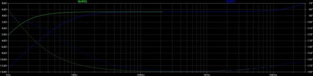
I'll attach one image, the blue one is the original the green one my actual configuration. Probably nothing we can notice, but i wanted to check how the caps i installed were changing the curve. If you change caps they will need some time to burn in.
Attachments
- Status
- This old topic is closed. If you want to reopen this topic, contact a moderator using the "Report Post" button.
- Home
- Amplifiers
- Class D
- Arjen's tube buffer for pre-amp