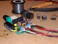
29 turns on two stacked T184-2 micrometals toroids, does anyone know a simpler or more compact approach? I don't. That's 100mJ energy storage!
Actually i saw ferroxcube gapped toroid and it has very less windings, they compared it with micrometal core indeed.......stacking the cores surely offers alternative solution.
Workhorse,
What is your load impedance? (8 ohms, 4 ohms, etc. speaker?)
2ohms and sometimes 1 ohm
But gapped toroids in the usual sizes don't get close to 100mJ, this is a lot of energy and trying to store it in a small gap results in problems. Remember that the biggest gapped toroid from Ferroxcube (26mm O.D. and lowest permeability) does just 1.5mJ
I usually prefer large OD cores like T225-2 which can take thicker wire for winding for high current applications and still compatible with 1U rack space height requirements, which cant be met with double stack cores due to incresed height.
Gapped Toroid offers EMI infernos from that "GAP" as a bonus also
Last edited:
I've been looking for some decent output inductors for my PBTL TAS5630 build, so this seems perfect.
http://focus.ti.com/lit/ds/symlink/tas5630.pdf
The switching frequency is 400khz. According to the data sheet a 10uH coil would be fine. And although I'm not entirely sure as to the absolute current requirement, the 1D14A-100M looks like it should do fine. Of course if you can recommend something else based on your expertise in this field, that would be great.
I would require 8 inductors for the stereo pair that I've built and I should be able to offer a subjective opinion. But I'd be more interested in the measurements I'd be making also.
The couple of inductors I've tried haven't been particularly good when it comes to distortion and higher power levels. So It would be great to try something built specifically for the job.
If you're interested, I'm in the UK and you should easily be able to email me through the DIYaudio website.
Thanks,
Matt.
I notice that gapped ferrite shielded core (used for classD filter) produces more heat than -2 material toroids, especially at area around the gap (it get hot around this gap area).Gapped Toroid offers EMI infernos from that "GAP" as a bonus also
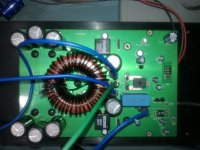
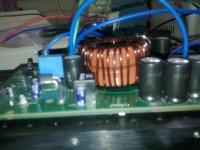
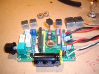
Hall effect sensor to measure output current?
Pulse transformers for isolated gate supplies?
Was the magnet wire so dark before high power testing?
Evita, yesssss
I found hall effect devices good for loss less current sensing and those pulse trafos you see are rated at 3kV isolation and have 12pF isolation capacitance, they were just for prototype unit.
The thicker polyamide enamel over wire gives it dark color.
Cheers......!!!
Last edited:
Looks dang-cool !!!
Do you use pre- or post-filter NFB ?
Regards
Charles
Thanxz Charles, ofcourse Post Filter Feedback
Ahhh - nice !
What topology - and how do you like it ?
Regards
Charles
Forced clocked......I love the sound, will give topology details on email
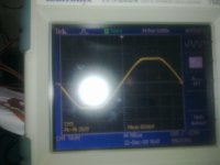
Check the clipping at 1Khz @ 2 ohms loaded
Attachments
Hi Workhorse,
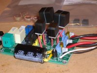
Do you have picture of the other side of the pcb?
No, that picture i lost somewhere
This is very nice clipping behaviour - without the slightest hint of rail-sticking.
Regards
Charles
Yeah..!!!
Actually the good control loop and some trick is at the work
some results
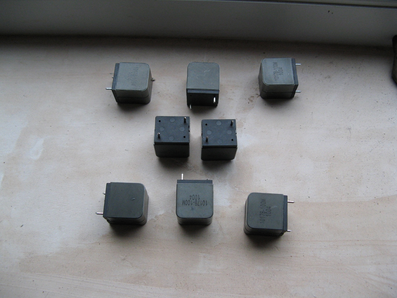
Its been about a week now of evenings swapping inductors sent to me by Ice Components for evaluation. I have got through the three pairs that they sent, objectively testing them.
I started with the smallest (physical size) units the 1D10A-100M, these I noticed a slight signal attenuation compared with the stock ferrite toroid inductors, but otherwise all three test samples were sonically very very similar.
I have no measurable results, purely audible. I think I was pretty thorough with my listening tests, playing many genres of music at various listing levels. Throughout my listening I found the sound produced was very transparent with no apparent colouration.
In my personal opinion, I would have no hesitation in recommending the use of this product.
PS. I am still considering winding my own air cores or air core toroids, unless of course someone has four in their junk box (10uH) that they would like to sell or trade???
Attachments
Hi Workhorse
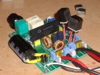
Looks super cool .. very compact
Like the way of putting all the leaded components on the ground plane side and ll the SMDs on the other ... makes for good ground plane and very compact design ..... by the way plane her is ground and not Vss, right .... have seen the advice from IRF on using Vss as plane for the outout secetion and GND for input ..... have been thinking about sot of doing both, meaning full GND on one side, and pouring as much Vss on the other side as possible ...
We're talking half bridge here, +-100V PSU and 5kW into 1 ohm .... right
Charles
At the moment playing with the scheme you presented a long time ago
http://www.diyaudio.com/forums/class-d/58448-simple-tweak-nfb.html
Works quite well
Thinking about making an additional loop outside, with a opamp in front .....
Anyway this was a thread about inductors .....
ICE_Mag, if you need more testers, I'll go for something like 20uH/10A or 40uH/10A
Looks super cool .. very compact
Like the way of putting all the leaded components on the ground plane side and ll the SMDs on the other ... makes for good ground plane and very compact design ..... by the way plane her is ground and not Vss, right .... have seen the advice from IRF on using Vss as plane for the outout secetion and GND for input ..... have been thinking about sot of doing both, meaning full GND on one side, and pouring as much Vss on the other side as possible ...
We're talking half bridge here, +-100V PSU and 5kW into 1 ohm .... right
Post filter, but clocked, not self oscillating?Thanxz Charles, ofcourse Post Filter Feedback
Charles
At the moment playing with the scheme you presented a long time ago
http://www.diyaudio.com/forums/class-d/58448-simple-tweak-nfb.html
Works quite well
Thinking about making an additional loop outside, with a opamp in front .....
Anyway this was a thread about inductors .....
ICE_Mag, if you need more testers, I'll go for something like 20uH/10A or 40uH/10A
Hi Workhorse
Looks super cool .. very compact
Like the way of putting all the leaded components on the ground plane side and ll the SMDs on the other ... makes for good ground plane and very compact design ..... by the way plane her is ground and not Vss, right .... have seen the advice from IRF on using Vss as plane for the outout secetion and GND for input ..... have been thinking about sot of doing both, meaning full GND on one side, and pouring as much Vss on the other side as possible ...
We're talking half bridge here, +-100V PSU and 5kW into 1 ohm .... right
Post filter, but clocked, not self oscillating?
Baldin, its multi layer board, top layer full GP i.e. GND and switching area is covered by VSS plane on middle layer, rest of middle and bottom layer being used for routing traces. Its +/-180VDC rail half bridge and 5KW in 2ohms.[
]Yes its post filter feedback topology and clocked at 270kHz.
and not self oscillating because the application demands sync, its not a diy oriented, its for serious high power pro-audio apps.
Last edited:
- Status
- This old topic is closed. If you want to reopen this topic, contact a moderator using the "Report Post" button.
- Home
- Amplifiers
- Class D
- Inductor Evaluation Help