I was going to post this in the "4*100 Watt Sure" thread, but I didn't want to hijack it with my ramblings. OK, here goes ") ...
...
My 4*100 Watt board has arrived and is sounding great. It only took 6 days to arrive from Sure (China) to the UK!
I'm currently testing it with some 1uF M-caps on the inputs and I'm very impressed with the sound. The stock caps (on the phono inputs) sounded quite "wolly" in comparison.
With the M-caps, the sound is crystal clear, but the frequency response still sounds very well balanced. The amp has a lovely amount of "kick" to it, and the mid-range sounds great on vocals. Personally, I think this amp already sounds a tad better than my RevC chipamps, and I'm currently only running the Sure amp using a crappy 20V 3A laptop PSU.
It's all looking (and sounding) good so far. The thing is, I'm planning to use two Sure amp modules in my DIY build (7.1 with DSP etc.), but I'm worried about hooking up my main speakers (M&K S-150's) to the Sure amp without any DC protection relays (especially since a couple of people on here have seen the "magic smoke" escape from their amps already).
I've searched the forum, but can't seem to find a DC protection circuit which is specific to the way the Sure amp is configured. If anything bad happens to my DIY amp, I'd MUCH rather the amp gets fried than my speakers, so I want the circuit to be very reliable...
I've knocked together a simple DC protect circuit on veroboard for testing, but I'm confused about the best / simplest way to implement this on a class-D type amp? My circuit seems to work fine for driving a relay directly and it disconnects the speaker when DC (or very low bass) is present. The problem is, I don't know how foolproof the circuit is?
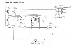
I've also attached a diagram of one of the DC protect circuits I found floating around the web.
My circuit is based on the first (DC protect) sections of the attached diagram, but with a resistor added to the second speaker input wire and with only one capacitor on the OUTPUT of the diode bridge. (I'll have to post a diagram at some point to make this clearer.)
What I realized with the Sure amp is that it still needs the bridge rectifier to be put across BOTH speaker wires because the amp is basically configured like a full bridge (I think?).
So, neither of the speaker outputs will have a negative voltage on them (with respect to ground), but they can still "swap polarity" in response to the input audio to achieve the output voltage swing (is this a correct way of describing it?).
Are there any ways of simplifying the DC protect circuit due to the fact that the neither speaker wire will go negative, or would something like a diode bridge always be necessary? I've searched the forum and have seen people talk about using a differential pair of transistors for DC detect, but how would this be implemented on the Sure amp? I know a few commercial amps which use a transistor pair, but I don't know how this could be applied to the Sure amp.
In the attached circuit, am I correct in saying that the emitters of Q5 / Q6 will need to be grounded, else they won't be able to pull the output signals low? Is there a good reason to use two capacitors on the protection inputs (to make a non-polarized cap) rather than a single cap placed AFTER the diode bridge? I know the diode bridge will produce a small voltage drop, but will using a single cap be a disadvantage to the circuit's operation?
Also, although this circuit has a diode bridge, it looks like it's still designed for amps which have one wire of the speaker output at 0V. When using the Sure amp with this circuit I think it would be a very good idea to add another resistor on the other speaker input wire, otherwise one "leg" of the amp will be connected to ground directly through the diode bridge!
(as a side note, some of you might have noticed that the LEFT channel input has a resistor but the RIGHT channel only has a resistor on the 0V wire?)
I'm only really interested in the DC protection parts of the circuit as I don't think the Sure amps require much of a turn-on delay. Although, it would be fairly simple to add a separate supply for the relays to eliminate turn-off thump from opamps and DACs if the AC power is removed.
Anyone have any thoughts on this type of protection circuit?
OzOnE.
...My 4*100 Watt board has arrived and is sounding great. It only took 6 days to arrive from Sure (China) to the UK!
I'm currently testing it with some 1uF M-caps on the inputs and I'm very impressed with the sound. The stock caps (on the phono inputs) sounded quite "wolly" in comparison.
With the M-caps, the sound is crystal clear, but the frequency response still sounds very well balanced. The amp has a lovely amount of "kick" to it, and the mid-range sounds great on vocals. Personally, I think this amp already sounds a tad better than my RevC chipamps, and I'm currently only running the Sure amp using a crappy 20V 3A laptop PSU.
It's all looking (and sounding) good so far. The thing is, I'm planning to use two Sure amp modules in my DIY build (7.1 with DSP etc.), but I'm worried about hooking up my main speakers (M&K S-150's) to the Sure amp without any DC protection relays (especially since a couple of people on here have seen the "magic smoke" escape from their amps already).
I've searched the forum, but can't seem to find a DC protection circuit which is specific to the way the Sure amp is configured. If anything bad happens to my DIY amp, I'd MUCH rather the amp gets fried than my speakers, so I want the circuit to be very reliable...
I've knocked together a simple DC protect circuit on veroboard for testing, but I'm confused about the best / simplest way to implement this on a class-D type amp? My circuit seems to work fine for driving a relay directly and it disconnects the speaker when DC (or very low bass) is present. The problem is, I don't know how foolproof the circuit is?
I've also attached a diagram of one of the DC protect circuits I found floating around the web.
My circuit is based on the first (DC protect) sections of the attached diagram, but with a resistor added to the second speaker input wire and with only one capacitor on the OUTPUT of the diode bridge. (I'll have to post a diagram at some point to make this clearer.)
What I realized with the Sure amp is that it still needs the bridge rectifier to be put across BOTH speaker wires because the amp is basically configured like a full bridge (I think?).
So, neither of the speaker outputs will have a negative voltage on them (with respect to ground), but they can still "swap polarity" in response to the input audio to achieve the output voltage swing (is this a correct way of describing it?).
Are there any ways of simplifying the DC protect circuit due to the fact that the neither speaker wire will go negative, or would something like a diode bridge always be necessary? I've searched the forum and have seen people talk about using a differential pair of transistors for DC detect, but how would this be implemented on the Sure amp? I know a few commercial amps which use a transistor pair, but I don't know how this could be applied to the Sure amp.
In the attached circuit, am I correct in saying that the emitters of Q5 / Q6 will need to be grounded, else they won't be able to pull the output signals low? Is there a good reason to use two capacitors on the protection inputs (to make a non-polarized cap) rather than a single cap placed AFTER the diode bridge? I know the diode bridge will produce a small voltage drop, but will using a single cap be a disadvantage to the circuit's operation?
Also, although this circuit has a diode bridge, it looks like it's still designed for amps which have one wire of the speaker output at 0V. When using the Sure amp with this circuit I think it would be a very good idea to add another resistor on the other speaker input wire, otherwise one "leg" of the amp will be connected to ground directly through the diode bridge!
(as a side note, some of you might have noticed that the LEFT channel input has a resistor but the RIGHT channel only has a resistor on the 0V wire?)
I'm only really interested in the DC protection parts of the circuit as I don't think the Sure amps require much of a turn-on delay. Although, it would be fairly simple to add a separate supply for the relays to eliminate turn-off thump from opamps and DACs if the AC power is removed.
Anyone have any thoughts on this type of protection circuit?
OzOnE.
Attachments
Last edited:
Actually, I just realized that putting the cap AFTER the diode bridge would mean that it is no longer an RC circuit.
On my circuit with only one cap, it only responds to fairly high voltages. The circuit didn't even trigger with a 4V battery across the input, so that can't be good.
I'll change it back to using two caps (non-polar) after the input resistors and see how it responds and I'll report back.
OzOnE.
On my circuit with only one cap, it only responds to fairly high voltages. The circuit didn't even trigger with a 4V battery across the input, so that can't be good.
I'll change it back to using two caps (non-polar) after the input resistors and see how it responds and I'll report back.
OzOnE.
Speaker protection module
I would just use one of the many ready made speaker protection modules that are available.
Speaker protection Board - eBay (item 190348617421 end time Nov-13-09 20:14:56 PST)
I would just use one of the many ready made speaker protection modules that are available.
Speaker protection Board - eBay (item 190348617421 end time Nov-13-09 20:14:56 PST)
Hi,
Nice work on the inductor replacements btw, I enjoy reading up on your mods.
I've looked into those boards before, and I know the UPC chip is a proven design, but do you think it would work properly for the Sure amp?
The root of my confusion is that the diagram in the UPC datasheet appears to show that the chip is designed mainly for amplifiers which have one of their speaker wires fixed at 0V (and the other wire usually goes both positive and negative). So, it can only detect DC on ONE speaker wire (referenced to ground) and not across the speaker wires?
This is true of many of the other DC protection circuits on the Web. Although, when a diode bridge is used, it should in theory work OK on the Sure amp?
(The protection modules on eBay suggest that they are "great for T-Amp's", but does this necessarily mean they will work on a bridged amp?)
Please let me know if the following is correct because I'm still trying to get my head around it all....
The Sure amp is configured as a full bridge, so if you wired it to a UPC chip like in the attached diagram, it can detect voltage on only one of the speaker wires at a time (it only shows one input resistor per channel).
I just tested the outputs of the Sure amp to confirm that each speaker wire output is actually at half the power rail voltage with no input signal. So, for my 19V power rail, both the positive AND negative speaker outputs are at 9.5V (when referenced to ground) with NO music playing...
This obviously gives a net voltage of 0V across the speaker (apart from the small DC offset of an unmodified amp ).
I don't think it would work to simply connect a resistor from both speaker wire outputs to the UPC chip because when both speaker wires are at the same voltage (say 9.5V again), the speaker will see 0V, but the voltage out of this resistor network will still be 9.5V when referenced to ground, and this will trigger the protection IC.
Attached is the diagram from the UPC datasheet - it shows how it would connect to a normal push-pull amp, but this type of amp only needs one of the speaker outputs to be monitored (the other is at 0V) - how would this work for a Sure amp when both "plus" and "minus" outputs are active??
I guess the solution would be to add another resistor (to the "minus" output wire), then add a diode bridge between the other ends of the resistors. The DC minus output of the bridge will be grounded, then the DC plus output will go to the UPC chip input. I think this should work OK, but I'm not 100% on this sort of stuff.
OzOnE.
Nice work on the inductor replacements btw, I enjoy reading up on your mods.
I've looked into those boards before, and I know the UPC chip is a proven design, but do you think it would work properly for the Sure amp?
The root of my confusion is that the diagram in the UPC datasheet appears to show that the chip is designed mainly for amplifiers which have one of their speaker wires fixed at 0V (and the other wire usually goes both positive and negative). So, it can only detect DC on ONE speaker wire (referenced to ground) and not across the speaker wires?
This is true of many of the other DC protection circuits on the Web. Although, when a diode bridge is used, it should in theory work OK on the Sure amp?
(The protection modules on eBay suggest that they are "great for T-Amp's", but does this necessarily mean they will work on a bridged amp?)
Please let me know if the following is correct because I'm still trying to get my head around it all....
The Sure amp is configured as a full bridge, so if you wired it to a UPC chip like in the attached diagram, it can detect voltage on only one of the speaker wires at a time (it only shows one input resistor per channel).
I just tested the outputs of the Sure amp to confirm that each speaker wire output is actually at half the power rail voltage with no input signal. So, for my 19V power rail, both the positive AND negative speaker outputs are at 9.5V (when referenced to ground) with NO music playing...
This obviously gives a net voltage of 0V across the speaker (apart from the small DC offset of an unmodified amp
).I don't think it would work to simply connect a resistor from both speaker wire outputs to the UPC chip because when both speaker wires are at the same voltage (say 9.5V again), the speaker will see 0V, but the voltage out of this resistor network will still be 9.5V when referenced to ground, and this will trigger the protection IC.
Attached is the diagram from the UPC datasheet - it shows how it would connect to a normal push-pull amp, but this type of amp only needs one of the speaker outputs to be monitored (the other is at 0V) - how would this work for a Sure amp when both "plus" and "minus" outputs are active??
I guess the solution would be to add another resistor (to the "minus" output wire), then add a diode bridge between the other ends of the resistors. The DC minus output of the bridge will be grounded, then the DC plus output will go to the UPC chip input. I think this should work OK, but I'm not 100% on this sort of stuff.
OzOnE.
Attachments
Last edited:
I would just use one of the many ready made speaker protection modules that are available.
Speaker protection Board - eBay (item 190348617421 end time Nov-13-09 20:14:56 PST)
I used a small cheap PIC for DC detect.
I just dropped the voltage using two resistors into the PIC i/o one pair for +ve phase and anotehr set for the -ve phase.
If the output stays >20 volts or < -20volts for 500mS then I drop the relay.
Using the PIC also means I can have a 3 second anti thump power up delay.
I use this circuit on my two disco amps and never blown a speaker due to DC.
I accidentally shorted the output once and blew the output transistor4s but the DC protect jumped in to save the speakers.
Bridged
Oh yeah, bridged. Thanks for reminding me. I am in the same boat as you. My ribbon tweeters will need relay protection. I will probably go with fuses for everything else.The Sure amp is configured as a full bridge
OzOnE.
I had thought about using a PIC once I have all the basics up and running.
I've actually used PICs a lot with various projects, but the irony is that I do like the idea of using "old skool" electronics for the DC detect part.
I want something that will be super simple yet very reliable. Then again, using a small PIC with an internal clock should be fairly simple and would work OK as long as the supply is stable.
You would still need a way of determining the voltage across the speaker wires on the Sure amp though. It seems that a diode bridge is still the simplest method....
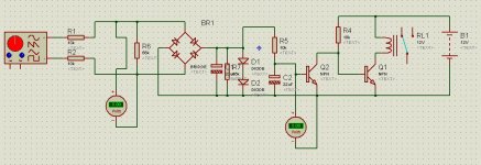
I've attached a diagram of the circuit I'm testing atm. Whether you put a 16uF cap before the bridge (non-polar), or a 33uF cap after the bridge (polar) the circuit appears to work in a similar way. The placement of the cap only appears to change the frequency response slightly - the relay will switch off with a sine wave of below 1.2Hz with 16uF and below 1.4Hz with 33uF.
Another issue is that, at low frequencies, the circuit needs around 8.5 volts across the speaker terminals before the relay will drop out! This bothers me because if the amp fails in a way which presents only 8V of DC across a 4 ohm speaker, this is still 2 AMPS of current!
OK, this next bit of rambling is quite off-topic, but I thought it might be of interest. Please let me know if I'm rambling too much again, I don't post very often!
I'm actually using the CPU and DSP boards out of a Denon receiver to decode 7.1 DTS / DD etc. So, if I can work out a reliable DC detect circuit for the Sure amp, I could use the orignal /PROTECT signal on the Denon CPU board to shut down the relays.
Atm though, I'm not comfortable with the way the DC detect circuit is working and I think using a PIC chip is quite a bit of hassle for something I'd imagine has been built a few times before (DC detect for bridged class-D)? Again, I did search the forum but I couldn't dig up much.
Basically, using a diode bridge should work in a very similar way on the Sure amp (no negative swing vs GND) as it does on a push-pull amp, but the fact it takes over 8 volts to trigger the protection is quite a scary thought to me.
As a side note: the DSP will eventually connect to my 8-channel Sabre DAC board (courtesy of NeoY2k) once I get the parts in. The DSP was previously running fine with in 2-channel stereo via my Buffalo DAC, but I wanted 8 channels.
I'm planning to build a controller with LCD UI for the amp from scratch. I need to figure out how the original CPU configures the DSP though. Once I've done that, I can control the DSP / DAC / volume / protection / inputs all from my own UI (with remote control).
Anyway, I digress (big time) ...
Does anyone have any ideas for reliable DC detect circuits for a bridged class-D? I'll look into the PIC idea though as I can simulate this before building.
Thanks for reading.
OzOnE.
I've actually used PICs a lot with various projects, but the irony is that I do like the idea of using "old skool" electronics for the DC detect part.
I want something that will be super simple yet very reliable. Then again, using a small PIC with an internal clock should be fairly simple and would work OK as long as the supply is stable.
You would still need a way of determining the voltage across the speaker wires on the Sure amp though. It seems that a diode bridge is still the simplest method....
I've attached a diagram of the circuit I'm testing atm. Whether you put a 16uF cap before the bridge (non-polar), or a 33uF cap after the bridge (polar) the circuit appears to work in a similar way. The placement of the cap only appears to change the frequency response slightly - the relay will switch off with a sine wave of below 1.2Hz with 16uF and below 1.4Hz with 33uF.
Another issue is that, at low frequencies, the circuit needs around 8.5 volts across the speaker terminals before the relay will drop out! This bothers me because if the amp fails in a way which presents only 8V of DC across a 4 ohm speaker, this is still 2 AMPS of current!
OK, this next bit of rambling is quite off-topic, but I thought it might be of interest. Please let me know if I'm rambling too much again, I don't post very often!
I'm actually using the CPU and DSP boards out of a Denon receiver to decode 7.1 DTS / DD etc. So, if I can work out a reliable DC detect circuit for the Sure amp, I could use the orignal /PROTECT signal on the Denon CPU board to shut down the relays.
Atm though, I'm not comfortable with the way the DC detect circuit is working and I think using a PIC chip is quite a bit of hassle for something I'd imagine has been built a few times before (DC detect for bridged class-D)? Again, I did search the forum but I couldn't dig up much.
Basically, using a diode bridge should work in a very similar way on the Sure amp (no negative swing vs GND) as it does on a push-pull amp, but the fact it takes over 8 volts to trigger the protection is quite a scary thought to me.
As a side note: the DSP will eventually connect to my 8-channel Sabre DAC board (courtesy of NeoY2k) once I get the parts in. The DSP was previously running fine with in 2-channel stereo via my Buffalo DAC, but I wanted 8 channels.
I'm planning to build a controller with LCD UI for the amp from scratch. I need to figure out how the original CPU configures the DSP though. Once I've done that, I can control the DSP / DAC / volume / protection / inputs all from my own UI (with remote control).
Anyway, I digress (big time)
...Does anyone have any ideas for reliable DC detect circuits for a bridged class-D? I'll look into the PIC idea though as I can simulate this before building.
Thanks for reading.
OzOnE.
Attachments
does your PIC project deserve it's own thread?I used a small cheap PIC for DC detect.
I just dropped the voltage using two resistors into the PIC i/o one pair for +ve phase and anotehr set for the -ve phase.
Sorry, I'll have to correct the part about the activation voltage... Under the Proteus sim, the signal generator doesn't produce anywhere near the selected voltage peaks. You also have to turn it down to 0Hz just at the right moment to "catch" it on a peak.
The peak voltage is only around 2.5V when the dial is set to 8V, so I don't think it's even related to RMS?
Anyway, I since replaced the signal gen with a pot and the results are more promising. The circuit only needs 2.2V of DC to turn off the relay.
The relay still drops out with around 2.2V whether you use a polar or non-polar cap (at least on the sim), but it will affect the corner frequency / response time slightly.
Could 2V of DC across the speaker cause much damage though? This is still around half an Amp on a 4 ohm speaker? (assuming a failed amp will still supply that much current).
This is why I hate it when people "tap-out" the speaker phase using a 1.5V battery. It must be doing some damage if it's held on for too long?
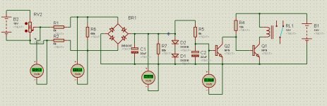
Attached is a better example of the circuit. The software doesn't show the forward voltage drop of the generic diode bridge, so there are quite a few variables to play with.
The peak voltage is only around 2.5V when the dial is set to 8V, so I don't think it's even related to RMS?
Anyway, I since replaced the signal gen with a pot and the results are more promising. The circuit only needs 2.2V of DC to turn off the relay.
The relay still drops out with around 2.2V whether you use a polar or non-polar cap (at least on the sim), but it will affect the corner frequency / response time slightly.
Could 2V of DC across the speaker cause much damage though? This is still around half an Amp on a 4 ohm speaker? (assuming a failed amp will still supply that much current).
This is why I hate it when people "tap-out" the speaker phase using a 1.5V battery. It must be doing some damage if it's held on for too long?
Attached is a better example of the circuit. The software doesn't show the forward voltage drop of the generic diode bridge, so there are quite a few variables to play with.
Attachments
does your PIC project deserve it's own thread?
Sounds like a good idea. Is it similar to the one on Rod Elliot's site?...
Project 111 - PIC Based Speaker Protection
This one could probably be used on the Sure amp if the inputs were modified with diode bridges.
OzOnE.
Sorry, I'm having a "stupid day" today...
The signal gen in the sim software works fine - The voltage dial sets the "peak-to-peak" voltage (ref. to GND), so the voltage across the pos and neg pins are of course at exactly HALF of the p2p voltage.
Also, the circuit does NOT work properly without using a non-polar cap (or two electrolytics back-to-back) directly BEFORE the diode bridge. This forms a proper RC circuit.
With only one cap placed after the diode bridge, the circuit responds more like a peak detector, (so the relay will chatter all the time when playing at higher volumes.)
So, the circuit above actually works quite well with a non-polar cap of around 16uF placed BEFORE the diode bridge.
With 6K input resistors and a 16uF cap, the relay cuts out at 1Hz if there is a 2.6V pk-to-pk signal ACROSS the speaker wires.
(The "bridged class-D" stuff and the simulation is confusing, because there really is only 2.6V ACROSS the speaker wires at the peaks and not 5.2V as it says on the dial).
I can't test it at higher voltages because the sig gen in the software doesn't go higher than 6V. But, you can visualize how the graph of "voltage vs frequency" would pan out.
I'm not good with calculating or plotting this stuff on graphs, so if anyone has any pointers?
If you use a similar circuit on the Sure amp, you should be able to find the best response time by adjusting the corner frequency.
Also, remembering that your input cap acts as a HPF, the relay shouldn't cut out during normal music playback (unless the amp's output frequency drops below your input HPF cutoff frequency.)
In other words - at or below 3.3Hz, the relay will still cut out when there 6V peaks across the speaker wires. To stop this happening during normal music playback you'll need to adjust the cap in the circuit depending on the HPF formed by the combination of your input capacitance and the amp's input resistor (100k I think?).
If the amp then fails for some reason and suddenly presents 2.6V DC (or more) across the speaker output (in either polarity), the circuit SHOULD switch the relay off within around 400ms (with the current circuit). Please don't quote me on this though!
If you want to use this for tweeter protection (active setups), then I think you could make the circuit's RC corner frequency higher so the relay cuts out when the amp's output frequency drops too far below your tweeter's crossover freq?
I hope this makes sense. I never got on with AC theory at college, so this stuff is tough for me to work out!
OzOnE.
Right, I'm going to try to keep the typing down a bit and show something a bit more "practical" now.
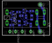
I've made a PCB layout for the DC protection circuit. I chose to use surface-mount components, as it doesn't use the very smallest parts so is still fairly easy to solder (I personally quite like soldering SMT stuff in most cases.)
The use of SMT components means that the PCB is not much larger than the relay itself! This should be good for confined spaces / multiple channels.
I've actually used a double-pole relay for each speaker as these were the type of relays I had left over from another project. I can easily change it for other layouts if anyone is interested?
The way it works is that it only switches the "positive" speaker output, but you still need to connect a wire to "negative" amp output for the circuit to detect the voltage across the amp output (We could call this the "sense" wire.)
It will also need a voltage supply for the relay, so you can choose this depending on the relay type.
The circuit should work for both bridged or standard push-pull / half-bridge amps (ie. common "negative" output). btw, the circuit should still work the same even if the input / output polarity is swapped.
A word of warning though, I haven't built this specific design yet, so they will need some basic testing (and tweaking of values) on first use, but should in theory work OK.
Attached is a picture of the PCB layout to give you the basic idea. I still need to order some components and maybe some PCBs to build these though. (I could make some DIY PCBs, but the quality usually isn't great.)
Would this type of module be of any interest to anyone?
OzOnE.
Attachments
I would expect a long term 1.5Vdc (>=100ms) to trip the DC detect circuit.i.e. a tap with a 1.5V battery should trigger the DC detect circuit.The circuit only needs 2.2V of DC to turn off the relay...........
...................Could 2V of DC across the speaker cause much damage though? This is still around half an Amp on a 4 ohm speaker? (assuming a failed amp will still supply that much current).
This is why I hate it when people "tap-out" the speaker phase using a 1.5V battery. It must be doing some damage if it's held on for too long?
I would also expect a 10Hz 20Vrms to not trip the DC detect circuit
I would expect a 20Hz 28Vrms to not trip the DC detect circuit fitted to a 100W into 8r0 amplifier.
1.5Vdc, from a battery to a 4ohm speaker (Re~3r0) will send ~750mW to the speaker voice coil. If your speaker cannot survive that for a half second or so then there is something wrong with the speaker you have selected to connect to a 100W amplifier.
2.2Vdc increases the voice coil power to ~1.6W
will the relay be capable of breaking the DC current in the event of a major output stage failure?
Will an input mute help to reduce the DC current that must be interrupted?
Will supply rails fuses help?
Have you considered supply rail crow bar protection?
 tbh, I haven't really looked into anything more advanced because I wanted something that would give the minimum basic speaker protection for amps like the Sure amp before hooking up to my speakers.
I have heard about the "diode" effects when connecting up relay contacts - I suppose it would be simple to change, but this type of thing gets a bit heavy for me. I mean, they use standard relays and fuses in most commercial gear (at the lower price range at least), so I could actually use a dual-pole relay for two channels, then add the DC detect circuitry to the same board.
This circuit is not meant to have ultimate protection for high-end amps, but it's way better than nothing on the Sure amp considering there have been a few "meltdowns" already.
I think it's always a good idea to calculate your average current consumption (and maximum amp output wattage) during music playback, then add fuses on the power rail(s) to protect against abnormal situations. I know many audiophiles don't like fuses or relays though, but we could be getting into snake oil territory there.
It would be nice to have all the extra protections possible, but this is all a bit beyond my skill level and budget tbh.
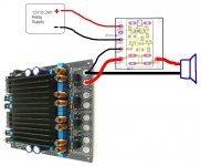
I've attached a rather amusing drawing of how this module would connect to the Sure amp (for anyone wondering). You can tell I'm no artist!
btw, the "/PROTECT" output is an active-low signal which could be used to tell a microcontroller which channel went into protect mode. This could also be used to shut off the relays on all the other channels at the same time (just in case the amp fails big time after the first channel pops.)
The /PROTECT line is connected to the relay supply via the 10K resistor and also via the transistors though, so I would probably use a zener on this line to limit the voltage before connecting to a CPU board.
Please keep in mind that I'm very much open to suggestions for this circuit, but my knowledge of this stuff only goes so far.
OzOnE.
Attachments
Hi, Andrew,
I just wonder why you don't often see DC protect circuits on the web which specify that they also work on bridged amps? This is very surprising to me.
Would you say that around 1.5V is the minimum DC voltage that you would want for the circuit to trigger? This should be fairly easy to achieve by playing with the cap / resistor values.
The problem is stopping the relay from dropping out with higher voltage sine wave / music. Now that I think of it, perhaps a zener diode could be placed after the input resistors to limit the maximum voltage across the cap? This might make the circuit less prone to trigger at higher voltages?
Using a zener is likely what I'd use if I had a PIC chip to monitor the speaker voltage. I would think that using a PIC should make the detection period the same for any voltage (above the diode bridge voltage drop and the PIC's input threshold of course)?
It would actually be quite simple for me to add a small 8-pin PIC chip to the relay board, but I'm always a bit paranoid to rely on a CPU for protection (even though this is the way of the modern World it seems.)
Looking at the PIC design on Rod Elliott's site, he has a table with some example LPF component values for different frequency / delay / voltage response times. So, in either case (simple LPF or LPF + PIC), it's still fairly tricky to select suitable parameters.
I'm wondering if it would be enough to instead just measure the length of the DC pulses from the diode bridge rather than rely on a LPF at all?
OzOnE.
I just wonder why you don't often see DC protect circuits on the web which specify that they also work on bridged amps? This is very surprising to me.
Would you say that around 1.5V is the minimum DC voltage that you would want for the circuit to trigger? This should be fairly easy to achieve by playing with the cap / resistor values.
The problem is stopping the relay from dropping out with higher voltage sine wave / music. Now that I think of it, perhaps a zener diode could be placed after the input resistors to limit the maximum voltage across the cap? This might make the circuit less prone to trigger at higher voltages?
Using a zener is likely what I'd use if I had a PIC chip to monitor the speaker voltage. I would think that using a PIC should make the detection period the same for any voltage (above the diode bridge voltage drop and the PIC's input threshold of course)?
It would actually be quite simple for me to add a small 8-pin PIC chip to the relay board, but I'm always a bit paranoid to rely on a CPU for protection (even though this is the way of the modern World it seems.
)Looking at the PIC design on Rod Elliott's site, he has a table with some example LPF component values for different frequency / delay / voltage response times. So, in either case (simple LPF or LPF + PIC), it's still fairly tricky to select suitable parameters.
I'm wondering if it would be enough to instead just measure the length of the DC pulses from the diode bridge rather than rely on a LPF at all?
OzOnE.
Hi, all,
Sorry to drag this thread up again, but I've just started looking at my amp project again because I recently bought a nice Tracopower 24V PSU for my 4-channel Sure amp...
(I've still never heard the Sure amp or my Sympatico amps on my 4-ohm speakers because I don't want to risk it without having basic DC protection.)
I'm still having major problems trying to figure out the best type of circuit for this amp...
Yesterday, I soldered four DPST relays onto a bit of veroboard (with their coil transistors and back-emf diodes), but I'm now wondering if something similar to the DC protect circuit I drew up (post 9) will be any good?
Does anyone know of the simplest way to implement DC protection for this type of class-D amp? The problem is that most protection circuits on the web are only for standard dual-supply / push-pull amps where one of the speaker output pins is almost always referenced (or connected) to ground.
With these single-supply "H-bridge" Sure amps, and a 24V supply, both speaker outputs sit at around 12V with no input / idle...
Does anyone know of a simple method of measuring the voltage "between" the two outputs, but still have the DC protect circuit referenced to ground?
@AndrewT - I've tried simulating a PIC chip protection circuit, but it kept falsely triggering the protection at certain input frequencies. Did you use the PIC's ADC to get a value for each speaker output voltage, then take the "difference" between the two values. Then, set a time delay if the difference stayed at DC for too long?
I'm having trouble visualizing how the PIC circuit would work for Class-D?
If anyone has any pointers, I would be very grateful.
I have a nice ES9008 8-channel DAC with 7.1 decoding and some new amps which have been sitting on a shelf looking very sad for the past few months. Please help!
OzOnE.
off the shelf
I'm going to try an off the shelf speaker protection module this weekend to see if it works. It should still work just referencing the + and - to each other. If dc is low between the legs as normal, it will connect. If one leg of the output went open it would have no reference and the other leg would be at full rail dc but the speaker would quit playing and wouldn't care. If one leg failed with a short the the dc sensor would sense full dc and go into protection.
I'm going to try an off the shelf speaker protection module this weekend to see if it works. It should still work just referencing the + and - to each other. If dc is low between the legs as normal, it will connect. If one leg of the output went open it would have no reference and the other leg would be at full rail dc but the speaker would quit playing and wouldn't care. If one leg failed with a short the the dc sensor would sense full dc and go into protection.
- Status
- This old topic is closed. If you want to reopen this topic, contact a moderator using the "Report Post" button.
- Home
- Amplifiers
- Class D
- DC speaker protection for Sure class-D amps?..