As far as the higher Rds and Qrr of the higher voltage part, it seems you have two choices. Either put up with higher switching and/or conduction losses or put up with it being fragile.
...or choose BCA topology, or disable body diode with series schottky and antiparallel FRED.
Cascode Output device... That work very well, get ride of switching lose and recovery issue..I have a design with +/-240V supply with STP62NS04Z as switching device, APT6011 (X2) as cascode device and IXYS DSEE30-12 as recovery diode....The cascode device use the +15V of each mosfet driver, so the switching device never see more than 11V between their D-S. That help a lot the miller capacitance in the same time...Just be carefull to dont switch ''too fast'', you should keep in mind the Dv/Dt of the cascoded device...Or use snubber over the switching device!
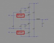
They are the cascode device...The switching is done by Q1 and Q3...See Q2 and Q4 as ''voltage regulator'' for Q1 and Q3...When Q1 or Q3 open, they ''disconnect'' source of Q2 and Q4 and the leg act as a ''normal'' single mosfet switch. In that configuration the switching '' speed'' are dertemined by the switching device and they only see at worst 12V between their D-S junction. The recovery diode of the switching device and the cascoded devices are in serie, so due to the hight voltage drop, nearly all recovery current flow trought D4 and D5, wich should be fast type..I wish that these simple explaination is clear.
I think the concept is good, but in the circuit diagram D1, D3, C1 and C2 are not in the right place. I have done the same for SMPS but with a bipolar transistor as the high voltage device (and a current transformer to feed the base).
Also, I think MOSFET choice is not good. How about PSMN1R7-30YL for the low voltage transistor, SPW47N60C3 for the high voltage one and STTH30R06 or FFP30S60S for the diode?
But the price paid for low reverse recovery charge in the diode are high diode conduction losses... And with SPW47N60CFD with only 2uC of body diode charge at 46A (25ºC, 100A/us) and the ability to bypass part of diode current with Rds-on, the advantage is not that clear... Ultrafast body diodes are not that bad.
btw: Why APT parts look like absolute junk on datasheets? They are overpriced yet easily outperformed by anything recent from IR or Infineon.
Your right Eva...the negative on cap should go to source of switching device....APT and IXYS device have proven themself to be very rugged in pro application...Equivalent parts from IR, Infineon and ST are lot more fragile for (nearly) same spec...I know it's not best arrangement, but 7 years ago, It was the only way I found to get 4 and 6 KW into 4 ohms! My 6Kw amplifier was running at +/- 240V with this topology...7 years ago, I was not using STP as switching device, but old IRFZ44!
How about PSMN1R7-30YL for the low voltage transistor, SPW47N60C3 for the high voltage one and STTH30R06
If you use a switching device with such a low resistance, then all of the voltage drops on the high voltage transistor, and at high reverse current its body diode will conduct almost the whole current. (Vf of the FRED is 1.1 V (typ), while Vf of the SPW47N60 is only 1V.) I would choose a switching transistor with higher Rdson, at least 20 mohms. (with the drawback of higher conduction loss, but I think it's better than a conducting diode with 200 ns (or more) recovery time.)
Or an alternative: you can monitor output current, and disable the transistor completely when the current is high and reversed.
Hi Pafi
You have made me think. I was assuming that the low voltage MOSFET would be turned off when current was negative. But then, if it is always on during conduction time for that side (for positive and negative current), it can be replaced by a fixed resistor whose value determines how much current is allowed through Rds-on and body diode of the high voltage MOSFET before the external ultrafast diode starts conducting. That resistor can be paralleled with a low voltage low Vf schottky for lower loss at high currents...
But how about SPW47N60CFD triplets? No body diode conduction until 20A, and at 60A body diodes would be conducting 30A (10A each) and Rds-on another 30A (75ºC) The amount of stored charge may be still manageable (I have done that with other MOSFET with lower Qrr).
Eva, the SPW cost nearly the same as the APT, no advantage in my circuit...But look better than any mosfet in half bridge standard configuration!
Pafi, when the switching device open, the recovery diode are in serie, ie 2X Vf. The cascoded device open as soon as the switching device open, since the switching device ''disconect'' the source of the cacoded device...If you still bug with the recovery diode, you can instead use High voltage transistor as direct replacement, or IGBT without recovery diode...
Pafi, when the switching device open, the recovery diode are in serie, ie 2X Vf. The cascoded device open as soon as the switching device open, since the switching device ''disconect'' the source of the cacoded device...If you still bug with the recovery diode, you can instead use High voltage transistor as direct replacement, or IGBT without recovery diode...
Pafi, when the switching device open, the recovery diode are in serie, ie 2X Vf
You've missed the 2 milliohms Rdson of Eva's recommendation for switching device. If it is on, then there is still 1*Vf.
the switching device ''disconect'' the source of the cacoded device
Actually it doesn't. It allows only 30...60 V change, depending on the breakdown voltage of the switching device. For the time interval while HV FET (or transistor or IGBT or body diode) is conducting, the current keeps flowing, with only 30-60V drop in output.
In reality the high voltage FET have to be fast, the only relief is it can have high gate-charge. And as we know, APT6011 is really fast indeed. Don't try it with a slow IGBT!
Hi Eva!
This way you got to the 'traditional' solution, but with linearisation. It is OK, and still not too complicated, but without the benefit of low gate-driver requirement of the cascode.
SPW47N60CFD is amasing, but I think it's still not better then a good IGBT in terms of efficiency even if only half of the current flows on diode. 10A @ 75 degrees @ 200 A/us Qrr is 1 uC, so it causes 500 uJ additional switching loss, wich is a little higher then total switching loss of HGTG20N60A4D at similar conditions. My personal favourite is HGTG20N60A4 + 15ETH03 (up to +/-150V).
...That resistor can be paralleled with a low voltage low Vf schottky for lower loss at high currents...
This way you got to the 'traditional' solution, but with linearisation. It is OK, and still not too complicated, but without the benefit of low gate-driver requirement of the cascode.
But how about SPW47N60CFD triplets? No body diode conduction until 20A, and at 60A body diodes would be conducting 30A (10A each) and Rds-on another 30A (75ºC) The amount of stored charge may be still manageable (I have done that with other MOSFET with lower Qrr).
SPW47N60CFD is amasing, but I think it's still not better then a good IGBT in terms of efficiency even if only half of the current flows on diode. 10A @ 75 degrees @ 200 A/us Qrr is 1 uC, so it causes 500 uJ additional switching loss, wich is a little higher then total switching loss of HGTG20N60A4D at similar conditions. My personal favourite is HGTG20N60A4 + 15ETH03 (up to +/-150V).
Pafi, the cascoded device dont conduct all the time! I think you dont understand how the circuit work....When the switching device open, it open in the same time the cascoded device, so only the recovery diode can conduct. The cascoded device cannot conduct when their source are open!
Pafi, the cascoded device dont conduct all the time!
Fredos
Who said it does?
I think you dont understand how the circuit work.
It was not me who attached a wrong schematic, and didn't want to realize it even after two warnings!

When the switching device open, it open in the same time the cascoded device
This is obviously not true. There is no miracle. To switch off a MOSFET its gate have to be discharged, and the charge carriers have to be sweeped off from the channel. Switching off an other FET won't do this automatically!
so only the recovery diode can conduct
Not only, but it definitely can, and this was my main point, so if you agree, then I don't undersand why are you arguing.
The cascoded device cannot conduct when their source are open!
1.: The cascoded device has gate electrode too (would you believe it?
), the drain current can (must!) flow there for a while (t=Qg/Id)! This is the basic of the "fast" operation, because Id can be several times higher then the current of a usual gate-driver.2.: The source is not open! A zener diode is not equal to an open switch. (Fortunately, because otherwise the gate would break down because of the -500V Ugs.)
That's partial schematic, just to got Idea...I forgot to add the discharge resistor between gate-source of the cascoded device...I just realise that these was important to understand principe....What I mean by ''open'' the cascoded device was open the complete leg...sorry, maybe too clear in my head! Dont whant to offense you, but I was thinking that you think that only the switching device was switching and the switching nod was only swinging of +/- 30V... Maybe just language mistake again!
Maybe just language mistake again!- Status
- This old topic is closed. If you want to reopen this topic, contact a moderator using the "Report Post" button.
- Home
- Amplifiers
- Class D
- 6000W By IRS2092