hello all,
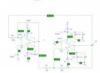
i've breadboarded a simple triangle generator as shown in the attached schematic, but the output at pin 1 just locks up to the negative rail, v+ goes to -0.7v, and v- stays at -5v!!! what is happening???
using a naiive opamp model (i'm using an ad823 on the breadboard), spice simulates this just fine as a 300khz squarewave at 10vpp and a 300khz triangle wave at 5vpp...
could this be something as dumb as my scope probe?
thanks...
~ brad.
Attachments
regarding the power supply, here is a pic (sorry for the quality):
tri01.jpg
the psu is two trafos with 12.6Vrms secondaries with primaries in parallel in mains, each of the secondaries goes to a rectifier bridge and the (+) of the lower bridge is tied to the (-) of the higher bridge at the 820uF filter caps to form ground. the unregulated +/-17Vdc is regulated by an LM7805 and an LM7905, each with 0.1uF ceramic caps on its input and output to ground. at no load the rails are +4.97V and -4.97V from the LM7805 and the LM7905, respectively. the ground from between the diode bridges is connected to earth ground.
let me know if i need to draw it... i probably will anyways.
as for the IC (AD823AN) getting hot, it doesn't. actually, none of the ICs do. it just locks up on the negative rail. i can't find any evidence of oscillation or loss of magic smoke...
~ brad.
Thank you for the picture and very good description. You won't need to to draw a schematic of the power supply, I understood your description. Seems fine to me. However, another uqestion: when you say you have 0.7V at v+ and -5v at v-, you mean pins 4 and 8 of the opamp?
If this is what you mean then obviously you've forgotten to connect the positive supply to the rail on your breadboard. Or the IC. From what I can see on the picture (by the way take the picture at a further distance I think that should make the focus better) you seem to have pins 4 and 8 going to a rail on each side of the breadboard, however I cannot tell if the top rail is connected.
Now another little thing I noticed was that 100pF seems pretty small to make an opamp oscillate at 300khz.
In any case I stick to my original theory: a wiring mistake from the power supply to the opamp.
thanks for the help! it turns out that in my haste to breadboard this thing, i miswired the PSU just enough to mess the whole thing up. now this baby runs great!
An externally hosted image should be here but it was not working when we last tested it.
thanks again, and sorry for the n00bish mistake!
~ brad.
Aha! that's what I thought! I knew you'd find it...
Nice job on the breadboard by the way. My breadboard is a battlefield of discrete and integrated components linked with spaghetti of different lengths
while we're on this subject, what's that oscilloscope?
Nice job on the breadboard by the way.
thanks, but even being tidy doesn't keep me from making wiring mistakes!
while we're on this subject, what's that oscilloscope?
it's an EZ OS-5060A 60MHz dual-trace analog. works great for everything i need.
~ brad.
hmm... well it runs now, but it's at 200khz instead of 300khz... any hint as to why this is occurring? it doesn't seem like scope probe capacitance or parasitic breadboard capacitance or part tolerances could do it alone... maybe altogether?
thanks for all the help!
~ brad.
thanks for all the help!
~ brad.
now a new issue: comparator rise-time?
ok, i've tweaked the component values to get a "close-enough" frequency of 275khz, which is good enough for a first class-d try on a breadboard.
BUT
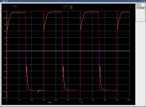
i've hooked an lm393 dual comparator to the triangle wave in order to generate a pwm waveform (positive comparator input is tied to ground for now) i get a really crummy square wave with a super-slow rise-time! my pull-up resistor is 5.9k (close to the datasheet value of 3.0k) and the power to the comparator is +/-12V. decreasing the pull-up to 470 ohms improves the rising-edge wave shape at the cost of cutting the bottom of the PWM wave at GND instead of -12V... is this comparator just too slow or is there a problem with its implementation?
the 'scope doesn't lie:
thanks,
~ brad.
ok, i've tweaked the component values to get a "close-enough" frequency of 275khz, which is good enough for a first class-d try on a breadboard.
BUT
i've hooked an lm393 dual comparator to the triangle wave in order to generate a pwm waveform (positive comparator input is tied to ground for now) i get a really crummy square wave with a super-slow rise-time! my pull-up resistor is 5.9k (close to the datasheet value of 3.0k) and the power to the comparator is +/-12V. decreasing the pull-up to 470 ohms improves the rising-edge wave shape at the cost of cutting the bottom of the PWM wave at GND instead of -12V... is this comparator just too slow or is there a problem with its implementation?
the 'scope doesn't lie:
An externally hosted image should be here but it was not working when we last tested it.
thanks,
~ brad.
the 'scope doesn't lie:
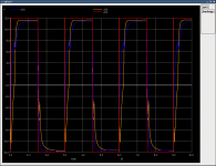
Actually it does. Probe capacitance makes rise time much higher, especially if you use 1:1 probe. Try 1:10, and 1k pull-up! (But I don't know why you need +/-12 V PWM.)
aha! thanks Pafi! you're absolutely right! not sure how that slipped past me.  rise time is greatly improved now. (+/-12V pwm is just really because it's a first attempt and i wanted to try directly driving the FET gates with the comparator... will the comparator output not be capable of supplying the required gate current to directly switch the FETs? (N-ch and P-ch complimentary.))
~ brad.
rise time is greatly improved now. (+/-12V pwm is just really because it's a first attempt and i wanted to try directly driving the FET gates with the comparator... will the comparator output not be capable of supplying the required gate current to directly switch the FETs? (N-ch and P-ch complimentary.))~ brad.
oh... i guess i kind of answered my own question...  the 1300pF input capacitance of the FET would cause the same sort of slow rise time as the scope probe capacitance, right? (you'll have to excuse my lack of expert knowledge here, the closest i've come to class-d is a boost converter for nixies...
  )
)
thanks again for all the help,
~ brad.
the 1300pF input capacitance of the FET would cause the same sort of slow rise time as the scope probe capacitance, right? (you'll have to excuse my lack of expert knowledge here, the closest i've come to class-d is a boost converter for nixies... )thanks again for all the help,
~ brad.
FIRST REVISION of discrete gate driver
ok, here's my first rough idea of what my gate driver should look like. the output FETs are IRF9540 and IRF640, since this is a first design and i'd like to stick with the simple for now.
spice shows interesting results, but i'm still not happy with the gate rising-edge waveforms... any optimizations or recommendations here?
oh and, since this is completely off the subject of the triangle generator, should this be in a new topic?
thanks,
~ brad.
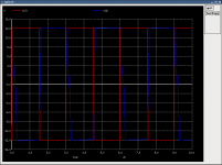
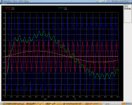
p.s.: thumbnails below: mpsa42/mpsa92 emitters, mosfet gates, pre-filter output.
ok, here's my first rough idea of what my gate driver should look like. the output FETs are IRF9540 and IRF640, since this is a first design and i'd like to stick with the simple for now.
spice shows interesting results, but i'm still not happy with the gate rising-edge waveforms...
any optimizations or recommendations here?oh and, since this is completely off the subject of the triangle generator, should this be in a new topic?
thanks,
~ brad.
p.s.: thumbnails below: mpsa42/mpsa92 emitters, mosfet gates, pre-filter output.
Attachments
Last edited:
well, the simulation and real life differ, i'm not surprised.
i guess it would be smart to head back to the drawing board completely, maybe by trying the gate driver ICs from IRF, considering its ease of implementation...
well foo, everything was working until i got to the gate drivers...
~ brad.
i guess it would be smart to head back to the drawing board completely, maybe by trying the gate driver ICs from IRF, considering its ease of implementation...
well foo, everything was working until i got to the gate drivers...
~ brad.
Attachments
ok, here's my first rough idea of what my gate driver should look like. the output FETs are IRF9540 and IRF640, since this is a first design and i'd like to stick with the simple for now.
The generall idea is OK. But Dgh must be reversed. And this schematic will produce 24V pulses on the mosfet gates (although usually the limit is 20V).
Also, the using of IR2110 is a common way to implement the class D output stage. And it will give you much more possibilities to made the next steps in your expremeting and education
A screenshot of the circuit would help. Just a wild guess would be that you swapped the comparator inputs.Hi, im trying to replicate this Triangle wave generator. I drew the circuit in PSpice, however, when simulated I'm getting a step instead of a triangle wave. Any suggestions on how to correct that to prove that the circuit works before I build it manually?
- Status
- This old topic is closed. If you want to reopen this topic, contact a moderator using the "Report Post" button.
- Home
- Amplifiers
- Class D
- simple triangle generator driving me mad!!!