@TracyB Check the supply voltages ")
@Thread TI has a nice document describing this circuit: http://www.ti.com/lit/ug/slau508/slau508.pdf
@Thread TI has a nice document describing this circuit: http://www.ti.com/lit/ug/slau508/slau508.pdf
Last edited:
DC bias point calculation has found the only stable and balanced operating point.
Either trigger it with a starting impulse or define initial conditions.
With some good luck it might already be sufficient to disable the bias point calculation.
PS:
741 really is slow, not a good choice for a classD triangle.
Either trigger it with a starting impulse or define initial conditions.
With some good luck it might already be sufficient to disable the bias point calculation.
PS:
741 really is slow, not a good choice for a classD triangle.
Capacitor C1 looks awfully small. I suggest you replace it with 10 nF (10,000 pF) and see whether you get a reasonable looking triangle wave. If so, reduce C1 by a factor of ten and try again. If the triangle is too slow, reduce C1 some more and try a third time.
Start with "too slow but at least it works" and gradually work your way towards full speed operation. You may decide to discard the 741 ICs and replace them with TL071s or other, higher speed FET input opamps.
Start with "too slow but at least it works" and gradually work your way towards full speed operation. You may decide to discard the 741 ICs and replace them with TL071s or other, higher speed FET input opamps.
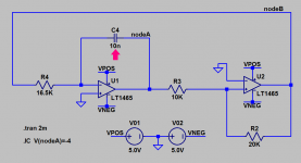
I put your circuit schematic into LTSPICE, except I substituted the LT1465 opamp instead of the 741. The LT1465 has got about the same GBW and the same slew rate as the 741, AND it is presupplied with LTSPICE. The 741 is not.
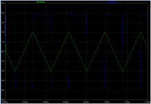
I used your component labels and your component values EXCEPT I changed timing capacitor C1 to 10nF. Everything worked. Maybe you can get your simulator to give these same waveforms when C1=10nF, using the 741 opamp simulation model.
edit- observe that the opamp output pins do NOT swing to the supply rail voltage in simulation. They don't swing to the supply rails in real life, either.
Attachments
Last edited:
I put your circuit schematic into LTSPICE, except I substituted the LT1465 opamp instead of the 741. The LT1465 has got about the same GBW and the same slew rate as the 741, AND it is presupplied with LTSPICE. The 741 is not.
I used your component labels and your component values EXCEPT I changed timing capacitor C1 to 10nF. Everything worked. Maybe you can get your simulator to give these same waveforms when C1=10nF, using the 741 opamp simulation model.
edit- observe that the opamp output pins do NOT swing to the supply rail voltage in simulation. They don't swing to the supply rails in real life, either.
Have you try it with 100 pF?
Do you have any information about simulation parameters in the two cases?
Chocoholic is right. Once any perturbance moves it out from balance, the oscillation must be started, no matter what the capacitance is. The simulation parameters are wrong.
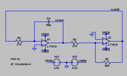
Using the same circuit schematic template shown in post #26, but with faster opamps and with lower impedance networks, I got the darn thing to produce 15 Megahertz triangle waves in LTSPICE simulation. Take a look at the circuit and the simulated waveform, attached below.
BEWARE these opamps are very expensive! (USD 3.22 @ qty 1, versus USD 0.42 @ qty 1 for the 741). Also beware, this circuit schematic operates the second opamp as a voltage comparator, which is usually a very bad idea! But it is the Original Poster's bad idea, not mine.
BEWARE these opamps are very expensive! (USD 3.22 @ qty 1, versus USD 0.42 @ qty 1 for the 741). Also beware, this circuit schematic operates the second opamp as a voltage comparator, which is usually a very bad idea! But it is the Original Poster's bad idea, not mine.
Attachments
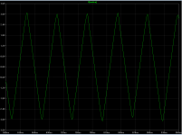
Waveforms in post#30 are swinging 6 volts in 33 nanoseconds, which is a slew rate of 180 volts per microsecond. Max9000 is rated for 1 volt per microsecond.Max9000 is a $3 chip SOIC8
Last edited:
- Status
- This old topic is closed. If you want to reopen this topic, contact a moderator using the "Report Post" button.
- Home
- Amplifiers
- Class D
- simple triangle generator driving me mad!!!