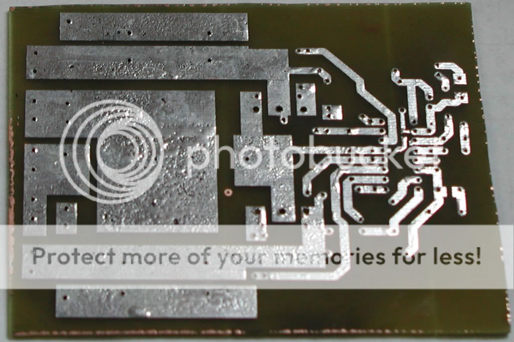
ok so I have done PCB, I think its ok, only thing now that I'm not sure of is how to connect powerGND with analogGND, the are seperated by -Vcc plane
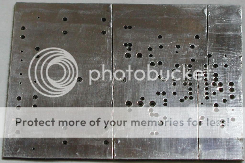
So one option 1. is via Ferrite Bead and 2. would be very easy to implement, all corners are mounting places, and those places, for now would be connected [one side is PGND, other side is AGND] via heatsink with screws.
Would 2nd option work, and how good?
So one option 1. is via Ferrite Bead and 2. would be very easy to implement, all corners are mounting places, and those places, for now would be connected [one side is PGND, other side is AGND] via heatsink with screws.
Would 2nd option work, and how good?
I can always do this, also I can do it via mounting studs (heatsink), resistor, bead,...I'd suggest running a wire from pin 2 of the IRS2092 to output (speaker) ground or input power connector ground. this worked well for me
I don't think anything can go wrong in any case, right?
I'd say yes, but...you would need to use fet drive cells, not IR itself, which would work up to +/-100... so, you'd have normal setup ith IR, but limit output so that is has lower max voltage, and use say 200v fet drive cells to drive fets with that high voltage
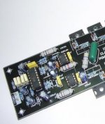
BTW: amp almost done, only IR and fets are missing
BTW: amp almost done, only IR and fets are missing
I'd say yes, but...you would need to use fet drive cells, not IR itself, which would work up to +/-100... so, you'd have normal setup ith IR, but limit output so that is has lower max voltage, and use say 200v fet drive cells to drive fets with that high voltage
BTW: amp almost done, only IR and fets are missing
Please shown the circuits diagram. Thankyou
So as it turned out, I won't have to wait until March, got 2092, and got 4227's, so I'm ready to move forward again. I will recheck everything, make sure its working
Apart from what setting for dead time to use, which I think I will have 75ns, which I hope is not that much, and not that little for fets, which are be the best I had so far.
And with freq. of about 250k, it should be up and running soon
Apart from what setting for dead time to use, which I think I will have 75ns, which I hope is not that much, and not that little for fets, which are be the best I had so far.
And with freq. of about 250k, it should be up and running soon
It works, kinda
I did expect freq. to be 250k, but with components used, (I assume I did not make any mistake), does only 93k
I will borrow this picture
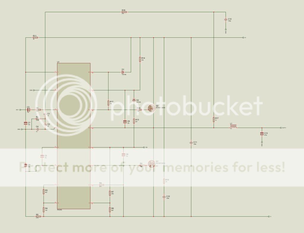
So based on this picture, I have
r17=1k
c12=1n
c1=c2=c4=2.2n
and R2=100 for 93k, and also tried 270 for 98kHz
Schematic is not totaly the same
I have "the same" as in Figure 26 in
http://www.irf.com/technical-info/appnotes/an-1138.pdf
One thing I also have is, limited voltage for IC, to 5.6V with zeners
What could be done? where to check for something? I hope c4 is not the problem, being 2.2n instead 1n
I did expect freq. to be 250k, but with components used, (I assume I did not make any mistake), does only 93k
I will borrow this picture
So based on this picture, I have
r17=1k
c12=1n
c1=c2=c4=2.2n
and R2=100 for 93k, and also tried 270 for 98kHz
Schematic is not totaly the same
I have "the same" as in Figure 26 in
http://www.irf.com/technical-info/appnotes/an-1138.pdf
One thing I also have is, limited voltage for IC, to 5.6V with zeners
What could be done? where to check for something? I hope c4 is not the problem, being 2.2n instead 1n
how can fets drop freq. like that? makes no sense to me. This is the best fet I could used and for that matter, only fet. I'm sure IRS can drive them just fine, since its not hot or anything. Its just about the same as ir2110, which had no problem driving stw34nb20, which has only 10nC less gate charge
you sure that C4 is not the problem here?
and gate waveforms look pretty damn good, both upper and lower
you sure that C4 is not the problem here?
and gate waveforms look pretty damn good, both upper and lower
Last edited:
hello friends, if is possible i want pcb desin this amp irs2092 my email cccv@inbox.lv
no I have gnd, that part I have, even if that schematic is wrong
C1,C2,C4 seem to be ok
after talking to Eva, which was totaly right on 2 counts, first being
2nd, this was not writen here, yet mentioned by odnaizutra is
that irs will have problems driving this fets, sure enough, this is right too
I mean it does work, but I don't think I would wan't it to run like that, without gate buffers
One thing I can say, self oscilating amp are hard to make, really, everything effect everything
But not type of fets, or better said, ther gate charge, that does not really change freq. that much, few kHz only
Still thinking what to do, do I run it a low freq, ~150k, change filter, or what... I know that I will need to change 2.7R resistor in RC filter at output, because its no good, then you have low freq, and you get +/-20v sine on output with switching freq
C1,C2,C4 seem to be ok
after talking to Eva, which was totaly right on 2 counts, first being
totaly, right... changed then cap in feedback network, from 1n, to 330n and some others, and sure enough, freq. went upCheck compensation and component values
2nd, this was not writen here, yet mentioned by odnaizutra is
that irs will have problems driving this fets, sure enough, this is right too
I mean it does work, but I don't think I would wan't it to run like that, without gate buffers
One thing I can say, self oscilating amp are hard to make, really, everything effect everything
But not type of fets, or better said, ther gate charge, that does not really change freq. that much, few kHz only
Still thinking what to do, do I run it a low freq, ~150k, change filter, or what... I know that I will need to change 2.7R resistor in RC filter at output, because its no good, then you have low freq, and you get +/-20v sine on output with switching freq
anything that cause any delay will change frequency ,you can read that at some ir apps.I know that a difference at qg of that size dont really change that much the frequency,but it affect.Try to use the right capacitors at front end and r2 as suggested.I see this kind of amp as an exercise to see how different things can affect the performance of the power amplifier.In some ir apps you can also find a table of differents values of c1,c2 and c4 and r2 in order to change frequency as you wish,i am not sure an1138.Any change at this caps really matter.But all of these are just suggestions because this ic is really hard to obtain a good result at first time.
- Status
- This old topic is closed. If you want to reopen this topic, contact a moderator using the "Report Post" button.
- Home
- Amplifiers
- Class D
- Irs2092