Hello. I'm kind of new in D-amps. I read the D-amp tutorial from IRF.com, I had a friend in the campus which builded one.
What I can't understand is the feedback loop in a D-amp. In a classic AB class the feedback is collected from the output back to the negative in of the amp and it akt's as a error correction.
But in D-class how can you take the pwm back into the analog in? The pwm will be mixed with the analog IN signal with is a sinwave.
Someone told me that that is trick to make a triangle wave and it ackts like an integrator. But these words doesn't have too much sens to me...
I can't understand what it happends step by step. Can anyone explain please how the loop works?
And why you will need a self oscillating topology? I mean this is not a T-class to self adapt the sample freq...
Practically my questions are regarding IRS2092 chip.
Attachments
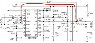
The ' pwm ' feedback is filtered back to analog by the action of the
47k resistor and then the capacitors to ground at the input.
One doesn't need self oscillation, but it is one approach.
This way the triangle wave (which is needed) is inherent
in the amplifier rather than having to be injected from
a separate source.
47k resistor and then the capacitors to ground at the input.
One doesn't need self oscillation, but it is one approach.
This way the triangle wave (which is needed) is inherent
in the amplifier rather than having to be injected from
a separate source.
The ' pwm ' feedback is filtered back to analog by the action of the
47k resistor and then the capacitors to ground at the input.
One doesn't need self oscillation, but it is one approach.
This way the triangle wave (which is needed) is inherent
in the amplifier rather than having to be injected from
a separate source.
Ahaaaaaaa GREAT EXPLANATION. Thank you so much man. You made the things very clear.
Thanks.
Yes, this kind of loop is a trick. And I think it's also hard to control. But...with simulations, and calculations of the transfer function of the loop I think it's possible to do it. From what I read extra about this loop is that it was invented to reduce the nr of components and using it you could have problems(ringing and so on ) at high power >1000W. So at this kind of power over 1kW I think it's better to use the classical triangle generator and the sinusoidal loop.
) at high power >1000W. So at this kind of power over 1kW I think it's better to use the classical triangle generator and the sinusoidal loop.selfoscillator or trw-modulator?
In theory, the amplifier can come right in the esoteric world is with triangular wave modulator. but ... since it is very difficult to do work well (snr, linearity, resolution high-frequency sound etc) then we prefer selfoscillator.yes is simple But has other defects")
Regards
In theory, the amplifier can come right in the esoteric world is with triangular wave modulator. but ... since it is very difficult to do work well (snr, linearity, resolution high-frequency sound etc) then we prefer selfoscillator.yes is simple But has other defects
Regards
Self oscillating loops have several interesting properties. For example, open loop gain is automatically compensated against changes in supply voltage, while in clocked modulators it's a direct function of supply voltage. This makes self-oscillating amplifier performance quite independent of supply rail voltage and sagging and improves PSRR dramatically.
Another advantage of self oscillating loops is that switching frequency is automatically reduced as the output approaches the rails, while keeping constant carrier residual amplitude at the output. This results in the minimum amount of switching events for a given carrier residual amplitude. In other words, switching losses are always as low as possible in self oscillating amplifiers. Switching frequency usually drops 2:1 or more before clipping.
Clocked modulators force the output stage to switch always at the same frequency, resulting in many switching events that are not really required, as the output gets closer to the rails and carrier residual amplitude becomes smaller and smaller.
Additionally, post-filter self-oscillating recycles the extra gain due to filter resonance as open loop gain, thus reducing output impedance (and THD too). In other words, the filter can resonate close to 20khz or even at a lower frequency without compromising frequency response.
Once you have put together a prototype which takes advantage of all this (and more), you don't feel like going back to clocked modulators.
Last edited:
Hi Eva,
I apologize to you for not having responded. but this is another fact).
ok, what you said is true though.
(Is that self-oscillating loops is Automatically Reduced switching frequency as the output Approaches the rails).
yes, this is one reason of Intermodulation audio signal, typically the mid range (vocals, trumpet, etc.) infact this defect is proportional to output power.
(Clocked modulators force the output stage to switch always at the Same Frequency, Resulting in many switching events That are not really required, as the output gets closer to the rails and residual carrier amplitude Becomes smaller and smaller.)
This makes no sense.because,while continuos clock if audio signal is smaller,current is smaller or zero. also this is very good because it is "sampleRate" it is necessary high and fixed for high performances.
My post ref to "absolute" Esoteric amplifier with two feedeback and active filter. it is not simple but I can assure you that you can not compare to a selfoscillator with post-filter feedback. (measurements and listening)
Regards
Last edited:
Self oscillating loops have several interesting properties. For example, open loop gain is automatically compensated against changes in supply voltage, while in clocked modulators it's a direct function of supply voltage. This makes self-oscillating amplifier performance quite independent of supply rail voltage and sagging and improves PSRR dramatically.
I have an working example of tri-wave generator, which compensates it's output amplitude and offset from supply rails, improving PSRR of clocked class-D amp dramatically too
Overall design surely becomes more complex, than in self-oscillating amp, but...Another advantage of self oscillating loops is that switching frequency is automatically reduced as the output approaches the rails, while keeping constant carrier residual amplitude at the output. This results in the minimum amount of switching events for a given carrier residual amplitude. In other words, switching losses are always as low as possible in self oscillating amplifiers. Switching frequency usually drops 2:1 or more before clipping.
I think, dropping down the switching frequency cannot have any positive effect for audio reproduction (at 10kHz-20kHz)
Once you have put together a prototype which takes advantage of all this (and more), you don't feel like going back to clocked modulators.
well, if the result is satisfying, sure you will not rebuild it
Your main misconception about PWM amplification is assuming that a non-constant switching frequency results in non linearity.
The absolute minimum switching frequency is 2 times the maximum frequency you want to amplify, 44Khz for 22Khz audio.
The main reason for using 10 times higher frequencies (400Khz) is being able to deal with carrier residual with a 12db/oct output filter.
In clocked modulators carrier residual amplitude is maximum near 0V output and drops to 0 when the output approaches the rails (ugly looking waveform btw). Carrier residual amplitude is modulated by audio signal.
In self-oscillating modulators carrier residual amplitude is almost constant and frequency is smoothly reduced to keep it constant. There is no penalty, it just takes advantage of a "feature" of the output filter that you can't use with a fixed clock.
This reduction in switching frequency does not involve any reduction in the amount of negative feedback, so linearity is unchanged.
Another advantage of variable switching frequency is spread spectrum EMI. Variable switching frequency is now being used in many SMPS control ICs. I nearly always use it in clocked modulators too, for example in PFC.
Last edited:
Hi,
discourse deviating from the central concept.
I absolutely assert that the Class D amplifier (esoteric performances) can not be selfoscillator, reliable and easy to develop. post-filter feedback , linearity, good thd Vs. frequency, better sn / r independent of the PCB.
Nyquest? simply says minimum fsample * 2 and what it has to do with esoteric amplifier?
You have heard ab class esoteric in an anechoic chamber?
Class D amplifier which you think sounds the same? I do not know of any amp that can sound the same.
ok, I assumed that I want to develop a new project that sounds the same as class-AB, it is obvious that I can not develop by selfoscillator scheme, the first defect is the intermodulation I said before. Because this can not be eliminated is intrinsic to selfoscillator. then it is convenient to deal with other problems that the TRW-modulator scheme. it is possible to solve with new circuit.
yes... the cost of development is not € 20 as selfoscillator.
what do you think has the real anomalies fixed-modulator?
Last edited:
Your main misconception about PWM amplification is assuming that a non-constant switching frequency results in non linearity.
It is not a misconception, PWM modulation itself produces some audible artifacts, whose amount depends on switching frequency (the higher Fsw, the lower amount of artifacts). It is why it is so important to keep Fsw as high as possible.
Here is a quote from Internet:
The PWM is known to create the distortion products that fall into the
audible band. If you use the double sided PWM, it eliminates some of the
distortion products, generally improving the overall situation (compared
to the single sided PWM at the same frequency). Still if you are looking
for the reasonably high fidelity audio, the PWM rate should be at least
500kHz.
Also, PCM really allows to select the sampling frequency using Nyquist theorem (Fsw = Fmax * 2), but PWM does not...
Last edited:
Hi,
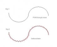
Please EVA ... eliminates the intermodulation from "Sig-2" because I feel perfectly on the voice of the singer when the power is over 50% on selfoscillator with post-feedback
Regards
If you think that the waveforms look like that, then fixed clock is ok for you
Also, if you want to make esoteric amplifiers, fixed clock is great for you too
Last edited:
It is not a misconception, PWM modulation itself produces some audible artifacts, whose amount depends on switching frequency (the higher Fsw, the lower amount of artifacts). It is why it is so important to keep Fsw as high as possible.
This is an over-simplification.
In fact, you got that quote here:
DAC using PWM | Comp.DSP | DSPRelated.com
But if you are using simplified expert replies to beginner questions as your design criteria, then fixed clock is ok for you
Self oscillating is delta sigma modulation. It's designed to produce the noise components above 20khz while using as little switching events as possible.
Triangle wave modulators do the same but are not optimized to use the minimum amount of switching events or to produce the noise components outside the audio band.
On the other hand, distortion due to dead time and other switching timing errors is proportional to switching frequency (considering the same circuit). In practice, increasing switching frequency increases dead time distortion, the worst type (like crossover distortion in class AB).
Last edited:
On the other hand, distortion due to dead time and other switching timing errors is proportional to switching frequency (considering the same circuit). In practice, increasing switching frequency increases dead time distortion, the worst type (like crossover distortion in class AB).
to EVA:
yes,
right this is the point of discussion. tringle wave is very difficult even if you have a strong preparation.
circuit requires new strategies.
driver does not exist on the market, so you develop it.
but this does not mean that it is better selfoscillator.
very simple...market is full of selfoscillator amplifiers!
After...I not think that waveform look like,but that waveform is without carrier frequency.
Last edited:
I think the opposite. The market is full of pre-filter fixed-clock triangle amplifiers. All work in the same easy-to-implement but sub-optimal way and suffer from the same pitfalls.
I use self-oscillating loops mainly because output impedance can be very low (well below 0.1 ohm even above 10khz), beacause frequency response can be flat and not dependent on load impedance (+/-0.1dB up to idle Fsw/10), and because switching losses are reduced (-30% or so).
I prefer a modulator acting more like an ideal voltage source, even at the expense of slightly higher THD in the last 3dB below clipping.
Additionally, no dissipative RC snubber is required at the output for stability, and thus, trebble output is not limited by resistor power dissipation.
Last edited:
Hi,
To EVA:
I know well the reasons that you explained about selfoscillator scheme, I fully agree with you.
the disagreement is only on an amp really esoteric.(not exist in the market)
The trw-modulator must not be interpreted as normal fixed frequency scheme.
this is obvious. But in innovative scheme, (Flat thd Vs.freq. load, independent response, high-resolution audio and good sn / r). This is the goal very difficult to obtain...very hard.. then exciting work!
I also have developed good innovative selfoscillator.
It would be great to have a long chat with you on some topics.
Snubber, Deadtime, delay from comparator to-gate MOSFET and new techniques for linearity and PSRR not documented in public.
Regards
Generally delta sigma modulation refers to the clocked version of the pulse density modulation scheme. However I guess the one you are mentioning is asynchronous delta sigma modulation (the one where the sampler is removed).Self oscillating is delta sigma modulation. It's designed to produce the noise components above 20khz while using as little switching events as possible.
However these types of self-oscillating, asynchronous circuits could produce idle tones which may appear inband.
- Status
- This old topic is closed. If you want to reopen this topic, contact a moderator using the "Report Post" button.
- Home
- Amplifiers
- Class D
- Difference between self oscillating and non-self oscillating D-amp.