Hi all,
I usally don't post much nowadays as i don't like to see the place cluttered up with lots of dead end threads but i really need some assistance here. I'm building my latest classD prototype and all is well. It's only a simple 200W half bridge fed off +-45V supplies. It works well, same as all my other clasD examples except i'm having the same reoccurent problem. The thing is... I've seem many people say in these forums that producing the triangle wave in a carrier based amp is the easy part. Well, either i have a small gap in my knowledge or physics is having a laugh at my expence.
The way i currently generate triangle waves is to use a CD4093, one gate for an RC oscilator ( usally around 250KHz ) and a second gate for a buffer. This squarewave clock i then feed into a 2.2nF cap through a resistor and thus... Triangle!
However this is a very crude way of doing things and there must be better ways out there. Using TTL helps a little due to its low impedance and high speed helping to keep the RF and other wee beasties out of the triangle but your limited to running TTL off 5V instead of split +-5v ( 10V ) that everything else runs off. I've tried all sorts of op-amp arrangments and they all fall down at high speed, even when using fast op-amps like the MAX412.
Anyway that i try always results in a reasonable triangle on the scope but when in use there are little whistling noises and other products inbedded in the wave. Can anyone shead some light on the mysterious triangle generation and maybe post some links or schematics as it must be so obviously easy that i must be overlooking the obvious and i'm finding it impossible to do LOL
HELP!!
Thankyou for reading
The problem is not because of the triangle wave. It is an interference, switching of one channel disturbs the other's comparator, and this way they modulates each other. What you hear is the difference frequency between the two oscillators. You should synchronize them! (I bet you actually built two channels. Turn off one of them!)
Last edited:
Think i'll try the suggested tri-generator that Stinius suggested. I've tried different coils on the board ( torroids and air cores ) just to rule out RF interference being thrown accross the PCB from the output filter or bridge.
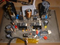
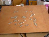
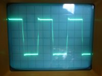
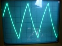
For your amusment i'll attach some piccys of the prototype pcb and the bridge and current triangle waveforms. As you will observe the ground is one solide copper ground plane and the track side has been implemented using tinned copper wire tacked down on matrix board, beefed up were needed by copper braid. The prototype doesnt require any heatsinking at all at the moment, dead times are approx 50n/s.
Does anyone think not using a Xtal accurate clock maybe influencing things?? The measured frequency doesnt seem to wobble although it does slowly drift up and down by a few hundred herts over time
Leigh
Attachments
Sure is an smps on board in the form of the LM switching regulator for the 45 to 9 volt drop to feed the 5v reg. I've tried isolating the +_5v rails and powering them seperate from a battery source but no luck. the only other thing that is switching in the room is the fet bridge so one must deduce that it is somthing to do with that. I'm convinced though that using a low impedance highly linear tri-wave should sort it out. After all if its the bridge interfering with the pwm stage then slowing that down is not an option
Leigh
Leigh
Do you mean the output stage interferes with its own triangle wave? It's impossible, since they have the same freq, and their phases are locked together.
Whatever happen, if it is periodic with the same freq as the triangle wave, it can cause DC error only. But what you hear is not DC error! You have to search for some error source that hasn't the same freq!
Whatever happen, if it is periodic with the same freq as the triangle wave, it can cause DC error only. But what you hear is not DC error! You have to search for some error source that hasn't the same freq!


Lol, The problem is definately on board and not an external source of interference. Looking at the cd4093 wavforms on the scope it seems the timing circuit has a much better square coming out of it than the buffer does. Also the timing caps waveform is an excellent tri-wave compared to the one being purposly generated due to the lack of drive from the buffer. I think i may be forced to redesign the tri-wave, or go to TTL and add some extra supplies. Either that or i could feed the timing caps waveform into the comparator, maybe buffer it first with an op-amp... Hmmm..
I've spent all afternoon trying all sorts of power rail filtering, nothing seems to effect the whining noises. The only thing that makes a real difference is putting ones finger near the cd4093 or touching the FET bridge. Thats why i'm convinced it's the poor way i've generated my triangle, thus this circuit must go!
Leigh
Pafi,
I'm not ignoring you. I value all suggestions and input in trying to get this problem sorted. The most benign or obvious suggestions may just be the key to this as it really does seem impossible for this to be happening. I've took all your comments into consideration and really do apreciate them and hope they keep coming as you or anyone else may just think of somthing obvious that i havn't thought of or tried yet. So keep those ideas coming
In the mean time i'm gonna try an external clock source to see if that helps. If not i must be overlooking some other means of intermodulation.
Leigh
Hmm, interesting...
Using an external clean clock, the amp seems to 'Tune' at regular frequencys. Around 150KHz, 200KHz, 250KHz ( the target freq ) 300KHz, 350KHz, you get the picture. Must be the carrier clashing with harmonics of anougher carrier, but what carrier?? There is no other switching aparatus in the room. It must be generated on board. The switching fets are well snubbed and there is hardly any ringing on the scope so it cant be that. Anyone any ideas?? This is cooking my noodles now.
Dunno if anybodys experienced this before?
Leigh
Leigh!
Thank you for being open minded, but please answer my question (PC on/off)! Please attach an exact schematic (including the possibly unconnected gates)! If you use energy saving lamp, or halogen with SMPS, then switch them off! What is the power supply of the amp?
Attach a loop antenna to your scope to discover any EMI source!
There is no computer in the room i do my work in. The power supply of the amp is linear, simple transformer - bridge - C R C, then onto the amp PCB. The lighting in the room is natural daylight. My scope and all other test equipment is also linear in its supplies and operation. I'll post a schematic in a few days. I need time to lay it out but time is not on my side as i work 15 hour days.
Loop antenna shows no signs of emi at all. Just the large fet bridge waveform.
Leigh
Loop antenna shows no signs of emi at all. Just the large fet bridge waveform.
Leigh
Last edited:
Loop antenna shows no signs of emi at all. Just the large fet bridge waveform.
If you see your switching signal with a loop antenna then this is definitely EMI as well ! It just depends on what and how much damage it makes !
Regards
Charles
- Status
- This old topic is closed. If you want to reopen this topic, contact a moderator using the "Report Post" button.
- Home
- Amplifiers
- Class D
- Producing Triangle Waves