A while back I scored several hundred TDK SMD 10uH ±20%, 0.0215 Ohm, 3.4 Amp, shielded inductors. (SLF12555T-100M3R4-PF: http://www.tdk.co.jp/tefe02/e531_slf12555.pdf).
I now find myself in need of a Class D o/p filter and can't help windering if I can make use of some of my stash! For a 100W/8Ohm application I seem to be looking for around 30uH that doesn't saturate at 5A.
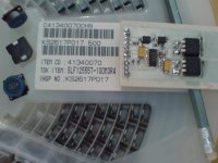
Observations about the inductor: The shielding comes down all the way over the bobbin carrying the coil but leaves a narrow gap top & bottom where it's glued together with some kind of blue resin. The winding is bifilar and the pair are 20cm long wound in ten turns.
http://www.tdk.co.jp/tvcl/equivalent/slf125xx.pdf also gives a parasitic R and C of 10k and 4pF.
So anyway, basic theory is fine with series/parallel connecting of inductors to arrive at different values - and shielding (if it works) should stop them interacting (!). I wonder if anyone can beat me to a conclusion before I slam 12 into two parallel strings of 6 to get 30uH @ 6.8A (DC 0.042 Ohm) and see how it goes?
Photo shows the parts alongside the bridge module I'm working on for my parallel Class A/D amp (thread at: http://www.diyaudio.com/forums/showthread.php?s=&threadid=148462)
I now find myself in need of a Class D o/p filter and can't help windering if I can make use of some of my stash! For a 100W/8Ohm application I seem to be looking for around 30uH that doesn't saturate at 5A.
Observations about the inductor: The shielding comes down all the way over the bobbin carrying the coil but leaves a narrow gap top & bottom where it's glued together with some kind of blue resin. The winding is bifilar and the pair are 20cm long wound in ten turns.
http://www.tdk.co.jp/tvcl/equivalent/slf125xx.pdf also gives a parasitic R and C of 10k and 4pF.
So anyway, basic theory is fine with series/parallel connecting of inductors to arrive at different values - and shielding (if it works) should stop them interacting (!). I wonder if anyone can beat me to a conclusion before I slam 12 into two parallel strings of 6 to get 30uH @ 6.8A (DC 0.042 Ohm) and see how it goes?
Photo shows the parts alongside the bridge module I'm working on for my parallel Class A/D amp (thread at: http://www.diyaudio.com/forums/showthread.php?s=&threadid=148462)
Attachments
sawreyrw said:There is no reason you can't use a series/parallel arrangement to do what you want, but it will take 27 of them.
Darn, I got my sums wrong! I edited it, but still got them wrong. This'll teach me to leave a party early on a Saturday night to get on with amp building

Sure ~ 3 'blocks' of 3x3 would give 30uH @ <=10.2A but with 0.063Ohms
|
LLL
LLL (10)
LLL
|
LLL
LLL (10)
LLL
|
LLL
LLL (10)
LLL
|
Maybe 2 'blocks' of 2x3 giving 30uH <=6.8A at 0.042 Ohms would be better:
|
LL
LL (15)
LL
|
LL
LL (15)
LL
|
Are my eyes decieving me? The parasitic capacitance would appear to go down by a factor of three in each case? That has to be good for class D use hasn't it?
Take some margin on current rating when using them in parallel. Inductance goes down with current below the actual full core saturation, so the one of lowest inductance in parallel connection takes the most current , which makes its inductance even lower.
This effect depends a bit on tolerance, but the ±20% you quote relates to the nominal value, not actual difference between any two of the same batch.
At DC the effect is however reversed, due to positive DCR coefficient due to heating.
(BTW both of your connection schemes result in the same DCR.)
This effect depends a bit on tolerance, but the ±20% you quote relates to the nominal value, not actual difference between any two of the same batch.
At DC the effect is however reversed, due to positive DCR coefficient due to heating.
(BTW both of your connection schemes result in the same DCR.)
Thanks! Many good points darkfenriz ~ yet while I'm still embarrassed about my drunken figures, the apparent reduction in parasitic capacitance still seems to be there. I'm about to build a test-bed with a PWM sig. gen and scope to characterise the results as this seems the best way to find out what I'll get anyway.
In my experience, wiring PWM output inductors in series results in resonance in the center tap nodes and thus somewhat higher EMI.
On the other hand, 27 inductors are a pain to mount and use a lot of PCB space. Consider getting some -2 micrometals toroids of suitable size and doing it with a single inductor.
On the other hand, 27 inductors are a pain to mount and use a lot of PCB space. Consider getting some -2 micrometals toroids of suitable size and doing it with a single inductor.
- Status
- This old topic is closed. If you want to reopen this topic, contact a moderator using the "Report Post" button.
- Home
- Amplifiers
- Class D
- Inductors in series/parallel?