The Crest circuit is quite ordinary I.e. it is not like the BCA. The inductors are in fact there to REDUCE shoot-through current but they would never allow an operational mode like the BCA, simply look ath their value: 200nH !
For further insight into this topology you might have a look at the following patents:
US patent #4178556 by Brian Attwood, "Class d amplifier system"
http://l2.espacenet.com/espacenet/bnsviewer?CY=ch&LG=de&DB=EPD&PN=US4178556&ID=US+++4178556A1+I+
US patent #4600891 Brian Attwood et al, "Digital audio amplifier having a high power output level and low distortion"
http://l2.espacenet.com/espacenet/bnsviewer?CY=ch&LG=de&DB=EPD&PN=US4600891&ID=US+++4600891A1+I+
You can see that they already used the hype expression "digital" back then in a false context.
Regards
Charles
Having read the referred patents, what seems to be a critical point to achieve low distortion is that the feedback signal must be as "clean" (free of the carrier ripple) as possible. The author uses LC notch filters, but they have some drawbacks.
On the other side, reading the On-Semi's app. note:
http://www.onsemi.com/pub/Collateral/AN1042-D.PDF
... I have noticed that they obtain the error signal by using a simple 1-pole lowpass filter (integrator) to mix the input and feedback signal (taken before the output filter). That should introduce a lot of ripple in the error signal that must cause noticeable distortion, shouldn't it?
The problem is that you cannot take the feedback from the output filter (4 pole = aprox. 80dB of attenuation in my case) due to the phase shift.
 I was thinking on using ON-Semi's app.note's topology but inserting a high order (i.e. MAX295 8th. order butterworth) at the ouput of the first opamp, thus having a CLEAN error signal to go into the comparator.
What do you think?
On the other side, reading the On-Semi's app. note:
http://www.onsemi.com/pub/Collateral/AN1042-D.PDF
... I have noticed that they obtain the error signal by using a simple 1-pole lowpass filter (integrator) to mix the input and feedback signal (taken before the output filter). That should introduce a lot of ripple in the error signal that must cause noticeable distortion, shouldn't it?
The problem is that you cannot take the feedback from the output filter (4 pole = aprox. 80dB of attenuation in my case) due to the phase shift.
I was thinking on using ON-Semi's app.note's topology but inserting a high order (i.e. MAX295 8th. order butterworth) at the ouput of the first opamp, thus having a CLEAN error signal to go into the comparator.What do you think?
The problem is that you cannot take the feedback from the output filter (4 pole = aprox. 80dB of attenuation in my case) due to the phase shift.
1.) Having a look onto the Crest schematic you will see that you in fact can do it !!!
If I were to design a new switching amp from the start, I would take at least a part of the feedback signal from after the main outupt filter.
2.) It depends heavily on the application how much carrier supression you want to achieve. Nowadys it is not regarded as that critical anymore to remove everything. This is only for EMC and cosmetics.
My thesis project back then had a carrier frequency of 250 kHz, an upper cutoff frequency of 45 kHz and 83 dB carrier suppression with a fourth-order elliptic output filter. So there's no need to use 8th order Butterworth filters.
Regards
Charles
Mmmm, thanks, Charles.
Did you use a 4 pole elliptic filter for the main output filter or for the error amplifier?
 So you have previously made a Class D amplifier?
Talk us a little bit about it. What output topology did you use? Did you have problems with shout-through? How much power did you obtain? And what about the efficiency?
It is always a pleasure to talk to something with REAL experience.
Did you use a 4 pole elliptic filter for the main output filter or for the error amplifier?
So you have previously made a Class D amplifier?Talk us a little bit about it. What output topology did you use? Did you have problems with shout-through? How much power did you obtain? And what about the efficiency?
It is always a pleasure to talk to something with REAL experience.
Nowadaysphase_accurate said:2.) It depends heavily on the application how much carrier supression you want to achieve. Nowadays it is not regarded as that critical anymore to remove everything. This is only for EMC and cosmetics.
the critical thing is how magic power cords and speaker wires and sticking out your tonge "improve" the sound. In the future it will be something else again. Hello all.
Weekly report #1
Last Saturday I was finally able to test my design of the PWM modulator with success. It is based on a MAX038 triangle wave generator adjusted to 200KHz, a LM837 opamp to amplify its output by a factor of 2 (4Vpp) and to form the error signal and then a LM319 comparator.
The intermediate signals and output are very clean. I trimmed the output PWM wave to measure exactly 50% duty cycle with no signal, and managed to get a rise time of 80ns and a fall time of 35ns.
Do you Class-D gurus think that this response times are good enough in order to pass to the next stage of the project (Mosfet drivers)?
Thanks in advance.
I can post an schematic soon if anyone is interested.
Some more thoughts...
One thing that worries me is feedback and output filter. Some designs take it from the speaker output, while others take it from the input of the output filter. The thing is that the output filter produces a phase shift at high audio frequencies. Below are the schematics of the filter I will try first: Chebychev 4 pole with 20KHz cutoff frequency. Attenuation is near 90dB at 200 KHz. Look at its phase response. It is more than 200 degree at the cutoff frequency. Won't this produce a problem when the feedback signal is substracted from the input signal?
And... another problem that I want to comment is that the output filter design is very dependant on the load impedance. If you design for 4 Ohms, you get a high frequency peak with a 8 Ohm load connected. Conversely, if you design for 8 Ohms, you loss high frequency with a 4 Ohms speaker. See the attached images (response with a 4 and 8 ohm loads for the filter, which is calculated for 4 Ohms)
If the feedback could be taken from the speaker output... won't it automatically correct this problem?
Charles, what can you say about these questions? Your opinion is very appreciated.
By the way... How do you insert images into this text?
Thanks
Attachments
The large phase shift of higher order filters is the reason why the main output filter of the amps taking feedback from- or after the filter use a 2nd order main filter.
Your Chebycheff filter would help you very much in building a nice (and even high efficiency ) ultrasonic generator.
Even if you don't take feedback from the output filter I'd recommend a 2nd order filter with a cutoff frequency higher than 60 kHz !! You may then add a notch filter to suppress the carrier frequency.
A higher filter cutoff frequency also makes your FR less load-dependant.
If you take feedback from or after the filter you'll have the following advantages:
- less load dependancy of FR
- less THD and IMD from the output filter (core saturation etc !)
- better transient response (i.e. risetime)
at the cost of the following disadvantages:
- less load independant stability
- amp is more susceptible to TIM
Regards
Charles
Your Chebycheff filter would help you very much in building a nice (and even high efficiency
) ultrasonic generator.Even if you don't take feedback from the output filter I'd recommend a 2nd order filter with a cutoff frequency higher than 60 kHz !! You may then add a notch filter to suppress the carrier frequency.
A higher filter cutoff frequency also makes your FR less load-dependant.
If you take feedback from or after the filter you'll have the following advantages:
- less load dependancy of FR
- less THD and IMD from the output filter (core saturation etc !)
- better transient response (i.e. risetime)
at the cost of the following disadvantages:
- less load independant stability
- amp is more susceptible to TIM
Regards
Charles
Thanks for your quick response, Charles.
 What you say makes sense: by rising the cutoff frequency and lowering the filter order you minimise the phase shift in the audio band so you can take feedback from the speaker.
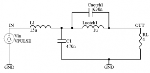
 But assuming a 200KHz carrier frequency, using a 2nd order, fc=60Khz filter, it leaves me with only 21dB of carrier attenuation. However, the phase shift at 20Khz (worst case) is about 22º, which seems acceptable.
Now, if I add a LC in parallel (see the attached image) I get a notch of -44 dB at 200KHz. Is this a good figure? It represents about 350mV rms of ripple assuming +/-50V rails.
The problem that I see here is that the notch is quite narrow, and any small drift in the carrier frequency will fall outside quickly.
Is this filter topology similiar to what you suggest?
Best regards.
What you say makes sense: by rising the cutoff frequency and lowering the filter order you minimise the phase shift in the audio band so you can take feedback from the speaker. But assuming a 200KHz carrier frequency, using a 2nd order, fc=60Khz filter, it leaves me with only 21dB of carrier attenuation. However, the phase shift at 20Khz (worst case) is about 22º, which seems acceptable. Now, if I add a LC in parallel (see the attached image) I get a notch of -44 dB at 200KHz. Is this a good figure? It represents about 350mV rms of ripple assuming +/-50V rails.
The problem that I see here is that the notch is quite narrow, and any small drift in the carrier frequency will fall outside quickly.
Is this filter topology similiar to what you suggest?
Best regards.
Attachments
You are on the right track.
What speaker impedance didi you design it for ? Just from Looks it seems to be made for a very low impedance or you will have quite a high Q with an 8 Ohms speaker (personally I would double the main inductor and halve the cap).
For the notch part I would also enlarge the inductor and decrease the capacitor. To avoid too sharp a notch I would connect a resistor parallel to the resonant circuit. I would also connect a cap around 10 nF parallel to the speaker output and also a Zobel network (or "things might get interesting" when the output is left open).
Regards
Charles
Well, I have designed it for 4 Ohms, althugh what I am trying to do first is to make sure that I understand the problems, I am not worried by the numbers yet.
Thanks. What is a reasonable rms voltage for the carrier ripple basing on your experience? (I assume that it is not audible however)
Thanks!
Thanks. What is a reasonable rms voltage for the carrier ripple basing on your experience? (I assume that it is not audible however)
Thanks!
Hi ssanmor
You are on the right track.
I would however take different values: Iwould double the inductance of the main filter an half the capacitor. The values shown might be good for a very low load impedance or you will have quite a high Q.
I would do the same thing for the notch filter. Additionally I would connect a resistor between 100 and 1000 Ohm in parallel to lower it's Q a little.
I would then add a smaller capacitor (between 1 and 100 nF) at the output to further improve suppression of the higher RF output spectrum.
And finally I would also connect a Zobel network at the output. Otherwise "things might get interesting"* if no load is connected to the output. Just keep in mind that a lowpass without any load is a series resonant circuit !!
If the 44 dB suppression is sufficient depends heavily on your application.
Regards
Charles
*copyright by N.P.
Hi ssanmor
Sorry for posting almost the same stuff twice. But I couldn't see my former post when I checked, so I assumed that something went wrong.
As already mentioned the desired carrier suppression is depending on your application.
If your application is a powerded subwoofer with good RF shielding you might get away with very little suppression (you then have to keep efficiency in mind because a speaker isn't a lLOW loss inductor).
The famous TacT MillenniuM amp for instance has a 2nd order output filter with a cuttoff frequency of 60 kHz approx (without any notch!). Try to imagine how much carrier suppression this leaves.
If you want to use long speaker cables you should be concerned about the part above 1MHz. If you want to efficiently get 200 kHz into the air you'd need a fairly large antenna ! Things change however as you get up infrequency.
But your 44 dB is quite a good starting point IMO.
Regards
Charles
Yes, Charles, the TacT Millenium uses a very simple filter which should leave a very high ripple. But, to be fair, we must say that it uses variable supply rails, so at low volumes, the ripple is also reduced, unlike a "conventional" (if this word is compatible with Class D) design, in which you get a constant ripple level, given by the supply rail voltage and the output filter attenuation at the switching frequency. (All this considered, I still don't think it worths 10000 dollars! ).
Returning to our discussion. My primary intend is to build a full range amplifier, not only for subwoofers.
As an important design parameter, I would like you to advice on what could be a reasonable maximum phase shift at the filter that can allow me to perform useful negative feedback if I take it from the speaker output.
Thanks.
I suppose you all are aware of this :
http://listen.to/audioexperiment
Vrey simple PWM amp, and a Danish Hi-Fi magazine says it sounds godd too.
Enjoy..
Koldby
http://listen.to/audioexperiment
Vrey simple PWM amp, and a Danish Hi-Fi magazine says it sounds godd too.
Enjoy..
Koldby
Yes, Koldby, Thanks.
I saw it a few days ago.
This design has several points to highlight:
 First of all, the modulator stage is quite odd: it doesn't use a triangle wave to generate the PWM modulation. On the other hand, it feedbacks the output signal (before filter), substracts it from the input audio and compares to 0. What is not clear for me is how to determine the oscillation frequency.
However, it uses P and N mosfets, what is not very adequate for high power levels. I was involved in a discussion it its corresponding forum about how to implement it with N devices only and we lead to a solution similar to the one used in the crest-LT amplifiers. (using a IR2110/2113 driver).
Referring to the output filter, the author highlights that he has wound his own coil instead of using a commercial one. What about using power inductors as the filter? Personally, I had chosen this: DMT3-35-12.
http://www.coi1craft.com/ds/dmt.pdf
As long as the maximum AC current is not exceeded, it should be OK, shouldn't it?
We will continue discussing.
Best regards to all the DIY'ers.
I saw it a few days ago.
This design has several points to highlight:
First of all, the modulator stage is quite odd: it doesn't use a triangle wave to generate the PWM modulation. On the other hand, it feedbacks the output signal (before filter), substracts it from the input audio and compares to 0. What is not clear for me is how to determine the oscillation frequency. However, it uses P and N mosfets, what is not very adequate for high power levels. I was involved in a discussion it its corresponding forum about how to implement it with N devices only and we lead to a solution similar to the one used in the crest-LT amplifiers. (using a IR2110/2113 driver). Referring to the output filter, the author highlights that he has wound his own coil instead of using a commercial one. What about using power inductors as the filter? Personally, I had chosen this: DMT3-35-12. http://www.coi1craft.com/ds/dmt.pdf
As long as the maximum AC current is not exceeded, it should be OK, shouldn't it?
We will continue discussing.
Best regards to all the DIY'ers.
Hi
I finally managed to get my old one scanned. An interesting fact is that the Danish guy used an almost similar approach for the gate drive as I did.
As soon as I have more time I will post some info what I did and why (including what I would do differently today).
Regards
Charles
I finally managed to get my old one scanned. An interesting fact is that the Danish guy used an almost similar approach for the gate drive as I did.
As soon as I have more time I will post some info what I did and why (including what I would do differently today).
Regards
Charles
Attachments
Ssanmor,
Actually I think that design is very interesting because of the "strange" modulator!
Aparently the switch freq. is determined by time constants (lags) in the feedback loop, but as long as it is high enough, it dosen´t really matter precisly what the freq. is, or what?
If it is sounding as good as the magazine says, it should be possible to improve it very much as the components used in (op-amps - comperator) is only half way decent.
Converting the output to a N only would be nice though.
Koldby
Hi
A member of the news group related to this "audioexperiment" PWM amp. has just come up with a link, better explaining the theory behind this particually design:
http://www.mueta.com/downloads/AES.PDF
Hope it will be helpfull.
I hope I do not intrrupt the main direction of this thread?
Koldby
A member of the news group related to this "audioexperiment" PWM amp. has just come up with a link, better explaining the theory behind this particually design:
http://www.mueta.com/downloads/AES.PDF
Hope it will be helpfull.
I hope I do not intrrupt the main direction of this thread?
Koldby
- Status
- This old topic is closed. If you want to reopen this topic, contact a moderator using the "Report Post" button.
- Home
- Amplifiers
- Class D
- My very first Class D pwm (switching) amplifier.