ssanmor, I have used two N-channel fets because
(1) I have lots of them and almost no matching P-channels
(2) You can get N-channel mosfets and IGBT's as big as you like. buahahaha..
The fets are driven by one each of International Rectifier IR2121 and IR2125 drivers. The provide isolation, good gate drive, level shifting so you can drive the upper fet, and current limiting.
RC filter? Yeah, I just wanted to see if I could get the thing working properly, not to make it super hi-fi or anything, so at the moment it sounds like reasonable quality AM radio.
charles, It has crossed my mind, and I haven't totally ruled it out but one thing that I am concerned about is the noise it would generate might find it's way into low level cct's and spoil the sound of the rest of the system. Ah well, nothing a magic power cord couldn't fix.")
jonathan, buahahaha..
(1) I have lots of them and almost no matching P-channels
(2) You can get N-channel mosfets and IGBT's as big as you like.
buahahaha.. The fets are driven by one each of International Rectifier IR2121 and IR2125 drivers. The provide isolation, good gate drive, level shifting so you can drive the upper fet, and current limiting.
RC filter? Yeah, I just wanted to see if I could get the thing working properly, not to make it super hi-fi or anything, so at the moment it sounds like reasonable quality AM radio.
charles, It has crossed my mind, and I haven't totally ruled it out but one thing that I am concerned about is the noise it would generate might find it's way into low level cct's and spoil the sound of the rest of the system. Ah well, nothing a magic power cord couldn't fix.
jonathan,
buahahaha..Now this IS an interesting thread! My friend and I almost split a tri-path amp module to try it out. but conflicting specs all over their site and a lot of marginal posts about them caused us to get cold feet.
But we are both interested in them and the hype around the bel-canto and the PS audio amps.
Good work Circlotron, and please keep us informed as it progresses.
Sheldon
PS I love your signature line.
But we are both interested in them and the hype around the bel-canto and the PS audio amps.
Good work Circlotron, and please keep us informed as it progresses.
Sheldon
PS I love your signature line.
>>ssanmor, I have used two N-channel fets because
>>(1) I have lots of them and almost no matching P-channels
>>(2) You can get N-channel mosfets and IGBT's as big as you l>>ike. buahahaha..
 Ohhhh! That sounds good! It is exactly what I want to do, but I don't figure out how exactly are the driver connected to provide the shift level. This is, for me, the most difficult part of the design. Could you provide more details or a schematic of the driver stage, please?
Thanks!
(And yes, you can get N-channel mosfets quite easily as samples
Best regards
>>(1) I have lots of them and almost no matching P-channels
>>(2) You can get N-channel mosfets and IGBT's as big as you l>>ike. buahahaha..
Ohhhh! That sounds good! It is exactly what I want to do, but I don't figure out how exactly are the driver connected to provide the shift level. This is, for me, the most difficult part of the design. Could you provide more details or a schematic of the driver stage, please?Thanks!
(And yes, you can get N-channel mosfets quite easily as samples
Best regards
Assuming that you can go from 0% to 100% duty-cycle, the ideal output power is ((Vcc*0.707)^2) /RL.
For example, for a 8 ohm speaker and +/-40V rails, you can theorethically get 100W.
In practice, it is a little bit less, taking into account the RDS(on) of the mosfets and the duty-cycle limit of your modulator (for safety, it should be somewhat limited from 5% to 95%, for example.
Hope this helps.
Circlotron,
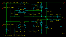
I have been investigating a bit about IR2121/25 drivers and it seems that the high side driver can work OK simply by connecting the outputs to the gate and source of the mosfet and the digital voltage and reference to, for example, +5V and 0V, so it's done.
The problem is with the low-side one. It seems that it cannot withstand negative voltages referred to COM terminal, so you have to connect this pin to the negative rail. This requires that the logic input is shifted and referrenced to ground.
Could you explain how did you accomplish that? Does your circuit uses any optocoupler? If so, could you draw the driver schematic?
Thanks in advance!!!
Thanks, Circlotron!
I hope that my request for the schematic hasn't bothered you. It is very kind by you to share it with us, because some people doesn't feel like showing their work. You can be sure that it won't be used for commercial purposes, I'am "only" a hobbist.
I will investigate on modifying the circuit for use with the IR2110 driver, that is readily available here, in Spain.
Best regards.
Sergio
Well, I have had a look at the schematic, and I think that it's conversion to IR2110 is straightforward.
Only a question more: The logic inputs are referenced to -50V, aren't they? So both of them switch from -50V (logic '0') to -38V ('logic 1').
I guess this conversion from the +/-12v or 12V outputs from the comparators can be done in at least two ways:
- Biasing the inputs of the drivers at -45V aprox. and couple the signal with a capacitor.
- Using a PNP transistor or P FET to do the level shift. (dc coupled).
Am I correct?
When I have time I will post the IR2110-converted schematic.
Thanks again and sorry for bothering you with so many details!
Yep.The logic inputs are referenced to -50V, aren't they?
Yep yep.So both of them switch from -50V (logic '0') to -38V ('logic 1').
I just used a separate supply to drive the low signal stuff and connected it's 0v line to -50v line of the power side of things. Makes everything so simple. You might have to draw a diagram of what you are suggesting.

I think that's fair enough since earlier on I was bothering everyone else in the thread about external speaker ports with my suggestions about making a truly ridiculous speaker. http://www.diyaudio.com/forums/showthread.php?postid=183455#post183455sorry for bothering you with so many details!
I guess this conversion from the +/-12v or 12V outputs from the comparators can be done in at least two ways:
- Biasing the inputs of the drivers at -45V aprox. and couple the signal with a capacitor.
- Using a PNP transistor or P FET to do the level shift. (dc coupled).
I'd suggest the second one or a combination of both.
Regards
Charles
Whel, now I think I have things much clearer. I have done some simulations and designed the level-shifter stage, based on PNP transistors.
I am going to build the PWM modulator with a MAX038 triangle wave generator and MAX912 comparators.
I will make it flexible so I can try the BCA and plain "half bridge" output stages.
Let's see how it works.
By the way, Circlotron, do you have measurements of the quality of the sound you are getting from the amp? I mean bandwidth, noise, etc. How does it sound at very low volume?
Have you tried to make it full-range (20Hz-20Khz)? Do you have much ripple?
I will post a proposal of the schematic as soon as I have drawn it.
Best regards.
ssanmor
May I give some suggestions:
If you use PNP transistors for the level shifting circuit:
1.) use them in commom base circuit and not common emitter
2.) don't turn them fully off during the "off" phases
These two measures should make the circuit faster.
Regards
Charles
May I give some suggestions:
If you use PNP transistors for the level shifting circuit:
1.) use them in commom base circuit and not common emitter
2.) don't turn them fully off during the "off" phases
These two measures should make the circuit faster.
Regards
Charles
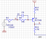
I would try to simulate the following for comparison:
Connect the base to ground and drive the emitter via a properly sized resistor. Connect another resistor from the emitter to the positive supply that keeps the collector current during the OFF phase at about 5% of the ON current.
Regards
Charles
Connect the base to ground and drive the emitter via a properly sized resistor. Connect another resistor from the emitter to the positive supply that keeps the collector current during the OFF phase at about 5% of the ON current.
Regards
Charles
Thanks,
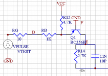
I have tried this (see image)
The results are nearly the same. The (on) current is 5mA, while the off current is 300uA.
The problem in both setups appears when you load the circuit. I don't know what the input capacitance of the IR2110 is, but with a 10pF load (CIN in the circuit), you get about 100ns rise/fall time, and it must be bigger, I am afraid. What do you think?
The advantage of the common-base circuit is that it doesn't invert the TTL signal.
Best regards
Attachments
- Status
- This old topic is closed. If you want to reopen this topic, contact a moderator using the "Report Post" button.
- Home
- Amplifiers
- Class D
- My very first Class D pwm (switching) amplifier.