At this webpage they have a formula to calculate the frequency of the triangle wave generator.
Your values;
Rt: 10k
R1: 33k
R2: 820k
would give a working frequency of 250kHz multiplied with (R2/R1) whick is approx. 621kHz. Is their formula wrong, or have you posted wrong values in the schematic?
Your values;
Rt: 10k
R1: 33k
R2: 820k
would give a working frequency of 250kHz multiplied with (R2/R1) whick is approx. 621kHz. Is their formula wrong, or have you posted wrong values in the schematic?
Hi Alcaid,
good question - I checked again, the resistor values and the capacitor are the ones I'm using. They are also still on the breadboard I used for testing. The question is now, if their formula is wrong (unlikely), or if I made a mistake measuring my frequency. On the other hand, I don't really believe that I drive my circuit at 620kHz... I guess I'll have to get the amp out, and measure again. Now I'm curious...
I don't have any experience with MAX wave generators. I found this one on google:
clicky
(that's for the MAX038, which seems to be quite nice)
I won't have time in the near future to build another amp. For the bipolar supply, nothing really changes. I'd leave the modulator with the virtual ground - the main reason for bipolar supplies is the power stage. It saves you bridging, so with the same design, you could drive 2 speakers independently (or you could save one half of the power stage). The speakers are then connected between the output for one half bridge (two fets with filter), and the center-tap of your power supply.
If you added another comparator for a second audio input, and drive the two IR2112s separately, you'd have a stereo amp without any effort.
The disadvantage is that the output amplitude is halfed. So for a 35V amplitude as I have it now, I'd need a -35V / 0 / +35V supply, which also means that the MOSFETs and the diodes have to withstand 70V. So you need less parts, but more expensive ones, since you are operating on higher voltages. Of course this also means more heat.
<* incredibly low output impedance/* load-independent>
") Really? How much? I've expecting about 25 damping factor for IDEAL power source and switching (3 meter of 1mm wire + 2*Rdson=.08ohm+.08ohm and no any kind of feedback). IMHO, THD on real speaker will be more 1% also. For sub applications 50-100khz switching is quite enough, and better for more efficiency.
Really? How much? I've expecting about 25 damping factor for IDEAL power source and switching (3 meter of 1mm wire + 2*Rdson=.08ohm+.08ohm and no any kind of feedback). IMHO, THD on real speaker will be more 1% also. For sub applications 50-100khz switching is quite enough, and better for more efficiency.
Really? How much? I've expecting about 25 damping factor for IDEAL power source and switching (3 meter of 1mm wire + 2*Rdson=.08ohm+.08ohm and no any kind of feedback). IMHO, THD on real speaker will be more 1% also. For sub applications 50-100khz switching is quite enough, and better for more efficiency. Hi IVX,
I probably shouldn't make claims I can't prove...
First, I don't understand your point about the MOSFETs. Yes, they have 50V breakdown voltage, and I drive them from a 35V DC unipolar power supply. The output voltage on the speaker is basically doubled by bridging. Just imagine a +/-17V bipolar supply with nothing connected to the center-tap. I wrote exactly this in my reply to Alcaid's questions.
(remark: oh cool, it is also possible to edit my own posts - should I remove this part now?!?)
For sub applications, a lower switching frequency would be sufficient. I wanted to have 250kHz to get some experience for a full range amp later. Since it works, I didn't change it anymore. Since I will get it out of my sub now anyway, to check some things, I might adjust it to 100kHz. The BCA principle virtually doubles this frequency anyway, so it still should be more than sufficient.
I can't comment on THD and impedance, since I didn't measure it. Just note that you don't have ANY problems or glitches at the zero crossing in BCA amps, and there is also no such thing as "deadtime". BCA amps are cleaner for low signals - less ripple, less distortion, etc. At higher amplitudes, distortion and ripple also grow with the amplitude, which is ok. At zero input, the BCA doesn't have ANY ripple at all, it cancels exactly out.
My outrageous claims regarding load independence came from some general views on Class D amps, partly from other people. It does make sense to me - the speaker is, in contrast to A or AB amps, not in a "variable resistor bridge", but the output voltage is mainly controlled by the duty cycles, and not really influenced by the speaker itself. In Class A amps, the voltage on the speaker depends very much on the resistance of the load (speaker), since the load is part of the "resistor bridge" that determines the voltage.
The overall "on" resistance of the switching output stage is very low, especially much lower than the resistance of the speaker. Also, inductive effects of the speaker/crossover/etc. can "flow off" over the freewheeling diodes. My conclusion is that the output voltage is more or less proportional to the duty cycle, and fairly independent of the load. At Class A Amps, it is not, and also at class AB amps, the load plays an important role.
This is all I can say about it - consider that I'm not an engineer, and I never learned how to calculate all this properly. Oh, and have you ever measured the THD of your speakers, or your room?
I probably shouldn't make claims I can't prove...
First, I don't understand your point about the MOSFETs. Yes, they have 50V breakdown voltage, and I drive them from a 35V DC unipolar power supply. The output voltage on the speaker is basically doubled by bridging. Just imagine a +/-17V bipolar supply with nothing connected to the center-tap. I wrote exactly this in my reply to Alcaid's questions.
(remark: oh cool, it is also possible to edit my own posts
- should I remove this part now?!?)For sub applications, a lower switching frequency would be sufficient. I wanted to have 250kHz to get some experience for a full range amp later. Since it works, I didn't change it anymore. Since I will get it out of my sub now anyway, to check some things, I might adjust it to 100kHz. The BCA principle virtually doubles this frequency anyway, so it still should be more than sufficient.
I can't comment on THD and impedance, since I didn't measure it. Just note that you don't have ANY problems or glitches at the zero crossing in BCA amps, and there is also no such thing as "deadtime". BCA amps are cleaner for low signals - less ripple, less distortion, etc. At higher amplitudes, distortion and ripple also grow with the amplitude, which is ok. At zero input, the BCA doesn't have ANY ripple at all, it cancels exactly out.
My outrageous claims regarding load independence came from some general views on Class D amps, partly from other people. It does make sense to me - the speaker is, in contrast to A or AB amps, not in a "variable resistor bridge", but the output voltage is mainly controlled by the duty cycles, and not really influenced by the speaker itself. In Class A amps, the voltage on the speaker depends very much on the resistance of the load (speaker), since the load is part of the "resistor bridge" that determines the voltage.
The overall "on" resistance of the switching output stage is very low, especially much lower than the resistance of the speaker. Also, inductive effects of the speaker/crossover/etc. can "flow off" over the freewheeling diodes. My conclusion is that the output voltage is more or less proportional to the duty cycle, and fairly independent of the load. At Class A Amps, it is not, and also at class AB amps, the load plays an important role.
This is all I can say about it - consider that I'm not an engineer, and I never learned how to calculate all this properly. Oh, and have you ever measured the THD of your speakers, or your room?
5 years ago i'd made similar amp but with feedback before filter, and achieved THD0.5%@100hz, damping factor about 200 and huge EMI around my DIYlab, which was partially reduced by many beads using.
You know, just a right now i made measurement for my system+room_ambient THD@about10W... 22hz - 4.8% (vented box resonance) and higher 100hz less then 0.8%.
BTW, how much THD of the microphone i don't know..
You know, just a right now i made measurement for my system+room_ambient THD@about10W... 22hz - 4.8% (vented box resonance) and higher 100hz less then 0.8%.
BTW, how much THD of the microphone i don't know..
Nice article if someone wants to learn more about class-D and output filters.
http://www.wictronic.ch/Downloads/C...tions assessdevice and filter performance.pdf
http://www.wictronic.ch/Downloads/C...tions assessdevice and filter performance.pdf
Hi IVX,
now, your THD Measurements are impressive, I must say. Especially 4% at 20 Hz are astonishing. Unfortunately my line-in of my PC picks up a lot of crap below 50Hz, so it's difficult for me to measure - at 20Hz I already have 4% directly from line-out back to line-in....
Over the speakers, I got around 1% at 100Hz (Chain: line-out - Amplifier (Marantz), Orbid Sound Supernova Speakers, Behringer ECM8000 Mic, Behringer UB1202 Mixer, Line-In), and between 0.7 and 0.2% from 200Hz upwards. At 10kHz it was 0.02%. While measuring my subwoofer, I noticed that it produces some distortion at very low frequencies, probably because the membrane breaks up, and produces harmonics. I guess I need a new speaker some day - they are just so expensive. The one I have now has ripples in the membrane - crap for subsonic use. Well, for now it does the job, at least until I got 200$ spare...
Alcaid, if you don't have a scope, I guess you can also simply adjust VGnd to V+/2, that's at least what it's supposed to be. My initial idea for that pot was to adjust the waves, such that at zero input the modulator waveforms are exactly balanced. This is important, to make sure there is no DC going through the speaker at zero input. It turned out, that a) it was already quite well balanced, and b) the pot didn't have such a big influence on that. I guess it's not that critical for correct operation.
In general, a scope is very useful for Class D amps, to verify correct modulation before you connect the FETs. Maybe you can find someone who has one, and go there once for tuning. I don't have one myself either, but I can use the ones at university.
Well, my school also have a lot of scopes, so I'll guess I could calibrate at school.
What if I adjust VGnd while measuring DC offset? That way I could trim for minimum output DC offset. Would that be a way to do it? I know, I'm trying to find shortcuts which doesn't exists....
What if I adjust VGnd while measuring DC offset? That way I could trim for minimum output DC offset. Would that be a way to do it? I know, I'm trying to find shortcuts which doesn't exists....
So if I dont need all the outputpower (150 w)I can leave out the triangle inverter and use one IR2112 and 2 Buz11,would I get about 75 w/4 ohm then,It saves you bridging, so with the same design, you could drive 2 speakers independently (or you could save one half of the power stage). The speakers are then connected between the output for one half bridge (two fets with filter), and the center-tap of your power supply.
is it possible to go as low as 2 ohm´s,what would the output be then?Shoul I connect the speaker to ground or VGnd?
Hello ryssen,
With or without bridging, the modulator stays exactly the same. You definitely need the triangle inverter, and both comparators!! The BCA idea is to generate in-phase PWM signals, which are both 50% dutycycle at zero input, and once the signal becomes greater or less than zero, then one PWM signal increases the duty cycle, while the other one symmetrically decreases its duty cycle. It's the difference between both, that determines the output.
If you don't want to use bridging, just leave one half of the power stage away, and use a bipolar power supply. Let's say you have a 24V transformer with a center tap. Rectified, this will give you -17V, 0, and +17V. To make it less confusing, let's set the reference to -17V, which is now GND. Then you have +17 and +35V. Connect 35V as drawn in the schematic, and connect the speaker and filter capacitor between the output and +17V. The current through the speaker must be true AC without DC bias, so you can't connect it to what I called GND in my schematic.
(Don't connect anything other than shown to VGnd! This is a bias on signal level only, you can't draw a lot of current from there! )
The output power will not be one half, but one quarter with the same power supply: P_max= V^2 / 2*R_load. So now the amplitude at the speaker is only 17V, makes app. 36W into 4 Ohms.
I guess you could also drive 2 Ohms, which should almost double the power. You will get very high currents, though, so make sure that all components in the power stage have a sufficient current rating. Also, add more caps! Obviously you will also get higher distortion levels with higher currents.
Commentable Thoughts
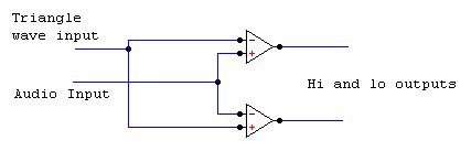
Hello SFX , i have gone through ur schematic , it looks very different as far as comparator is concerened . i think there is no need to get inverted Triangle output because using 2 comparators one can still achieve out of phase hi and low outputs
PLZ Glance on my circuit.
PLZ CORRECT ME IF I AM WRONG.
With regards
Ampman
Attachments
Commentable Thoughts
The previous Post applies when , we dont want to implement Crown's BCA topology.
In my case i dont want to use BCA Topology , thats why i have suggested that modification.
Secondly, Feedback is not present , can we say that THD levels are well below 1% without feedback or Feedback might be neccessary to reduce distortion as it requires additional error opamp.
AT last U said that BCA requires in Phase signals , if this is correct then the lo and hi inputs of individual gate drivers must be tied together and therefore there is no need of inverted triangle in case of half bridge operation. Only one comparator will do the job.
CORRECT ME IF I AM WRONG
with Regards
Ampman
Hi Felix,
Thanks again for providing us with your design!
Some hints if you want to go further:
Triangle:
I tried AD8033/8034 for the (synchronised) triangle generator, it was good for 500kHz, which I want to use as the base frequency. The circuit is to bee seen here:
Some oscilloscope pictures are available also, if you are interested.
Triangle inversion:
In my opinion it would be better to invert the input signal instead of the triangle inversion - much lower frequency requirements. Secondly I would take care of same delays, that means, to have nearly the same signal path for the noninverted and the inverted signal. I used a noninverting and an inverting amplifier to generate the inversion in my schematic, a differential output of the OPA would be an alternative.
GND:
I do not like virtual GNDs very much (already had a lot of trouble), mostly I try to realise a heavy and real good GND plane plus Pos/Neg supplies, if I have to provide balanced supplies. In your circuit does not flow any significant current through this node, so this may be ok. But it can pick up some noise because of the frequency dependent impedance.
Comparator:
Somebody of the other thread suggested the LT1711 as very fast comparators, they need a careful layout to prevent from spurious oscillation I believe.
Driver:
For the whole audio band you may need a higher switching frequency (especially without feedback), I would suggest the HIP2100/2101 therefore. It is much faster, stronger and exhibits well matched delays.
Dual supplies:
Why do you want to use a dual supply for the output stage? I find your design very advantageous. It would be a pity to complicate it by the complex SMPS and higher voltage requirements. Keep in mind, that the losses will increase with the square of the voltage. The FETs will have higher RDSon, the Diodes will have higher forward voltages and so on.
Again, that are only my thoughts, maybe, some are wrong or more or less academic.
Good luck for your studies!
By the way, you told something about a research submarine - that seems to be very interesting, I'm a bit envious.
Best regards, Timo
Hi Timo,
Thanks for your tips. I'll definitely have a look at the Wave Generator you suggested. Could you please check the link to the schematic? It doesn't seem to work.
The advantage with inverting the triangle instead of the signal is that you can use on modulator for many channels, you only add more comparators. Doesn't really matter in my design, though... it basically came from the fact that I used this Quad Opamp for the modulator, so a spare opamp was handy, and very close to the triangle output... it gave a nice and compact design without too many interwoven signal paths.
I also don't really like my VGnd solution, but I didn't see a better way for this specific amp. I wanted to have a singe power supply (well, I ended up with 2, one 12V regulated, and one 35V). My trafo just didn't have a balanced +/-5 secondary. My next amp will be some bigger, multichannel amp, and I'll by the transformer for it, so it will have proper balanced supplies. My main problem was coupling the Audio input to the circuit - it works fine over the capacitor, but at power on, there is some potential on the input, until the cap is charged. Not very nice... Also, I will design a PCB for the next one, so I can have a Ground plane, too.
And why dual supplies for the output? Mainly I wrote so much about it, because people kept asking about it. I also like my bridge design, that's why I made it. Nevertheless, in a multichannel amp, it's probably simpler to invest more into a dual supply, and save at the output stage. Afterwards, you can still bridge the outputs, if needed.
For the whole audio band, 250 kHz is enough. The professional Crown amps also have only 250kHz. If you have a close look at the BCA principle, you will realise, that the effective frequency is 500kHz.
Nominally, both PWMs are on at the same time, at 50% duty cycle, so they cancel each other out.
The output voltage is proportional to the difference in duty cycle between the two in-phase PWM signals. So you'll get a short pulse at the beginning, then both are on, so the result is 0, then again a short pulse. The base frequency doubles, but all active parts run at base frequency.
1.) no signal
____----____----____----____
____----____----____----____
output:
____________________________
2) positive signal
___------___------___------___
_____--_______--_______--_____
output:
___--__--___--__--___--__--___
good, ey? Shame that it's patented...
Regarding the driver, I think my solution with discrete FETs is ok. The IR2112 have matched delays (30ns, I think), and the signal paths to the gates are extremely short and of equal length. The MOSFETs are all the same - I just assume they have similar speed. Apart from that, the timing is not that critical, since deadtime or shootthrough doesn't exist in this design. The only thing you will maybe get with mismatched delays is a slight DC offset, but I couldn't find any in my prototype. I'm a big fan of BCA - nothing can go wrong
Cheers,
Felix
PS: yeah, my little submarine is absolutely interesting! Here's a link, if you're interested: click here
The case of the amp is of course not from this one, but an old one from our bigger sub: bigger sub
Commentable Thoughts
As a manufacturer i will not use BCA topology because i.e. will be a cheating, which i dont like.
with regards
ampman
sfx said:Hi Timo,
Thanks for your tips. I'll definitely have a look at the Wave Generator you suggested. Could you please check the link to the schematic? It doesn't seem to work.
The advantage with inverting the triangle instead of the signal is that you can use on modulator for many channels, you only add more comparators. Doesn't really matter in my design, though... it basically came from the fact that I used this Quad Opamp for the modulator, so a spare opamp was handy, and very close to the triangle output... it gave a nice and compact design without too many interwoven signal paths.
I also don't really like my VGnd solution, but I didn't see a better way for this specific amp. I wanted to have a singe power supply (well, I ended up with 2, one 12V regulated, and one 35V). My trafo just didn't have a balanced +/-5 secondary. My next amp will be some bigger, multichannel amp, and I'll by the transformer for it, so it will have proper balanced supplies. My main problem was coupling the Audio input to the circuit - it works fine over the capacitor, but at power on, there is some potential on the input, until the cap is charged. Not very nice... Also, I will design a PCB for the next one, so I can have a Ground plane, too.
And why dual supplies for the output? Mainly I wrote so much about it, because people kept asking about it. I also like my bridge design, that's why I made it. Nevertheless, in a multichannel amp, it's probably simpler to invest more into a dual supply, and save at the output stage. Afterwards, you can still bridge the outputs, if needed.
For the whole audio band, 250 kHz is enough. The professional Crown amps also have only 250kHz. If you have a close look at the BCA principle, you will realise, that the effective frequency is 500kHz.
Nominally, both PWMs are on at the same time, at 50% duty cycle, so they cancel each other out.
The output voltage is proportional to the difference in duty cycle between the two in-phase PWM signals. So you'll get a short pulse at the beginning, then both are on, so the result is 0, then again a short pulse. The base frequency doubles, but all active parts run at base frequency.
1.) no signal
____----____----____----____
____----____----____----____
output:
____________________________
2) positive signal
___------___------___------___
_____--_______--_______--_____
output:
___--__--___--__--___--__--___
good, ey? Shame that it's patented...
Regarding the driver, I think my solution with discrete FETs is ok. The IR2112 have matched delays (30ns, I think), and the signal paths to the gates are extremely short and of equal length. The MOSFETs are all the same - I just assume they have similar speed. Apart from that, the timing is not that critical, since deadtime or shootthrough doesn't exist in this design. The only thing you will maybe get with mismatched delays is a slight DC offset, but I couldn't find any in my prototype. I'm a big fan of BCA - nothing can go wrong
Cheers,
Felix
PS: yeah, my little submarine is absolutely interesting! Here's a link, if you're interested: click here
The case of the amp is of course not from this one, but an old one from our bigger sub: bigger sub
As a manufacturer i will not use BCA topology because i.e. will be a cheating, which i dont like.
with regards
ampman
Hi Felix,
I do not believe, that you want to sell your solution, so you may use patented designs as well. There is no cheating risk.
Look at that forum:
http://groups.yahoo.com/group/switchmode
Files > Miscellaneous Circuits > NBDD Modulator > d_amp023.pdf
Ok, you're right with the triangle inversion, saw it already in the AES-papers.
Unfortunately I did niot bring "my" HIP2100s to work already due to a lack of time scheduling
But I like them, take a look into their datasheet, the data are as impressive as their pricing (also available at Farnell).
Best regards, Timo
Hi,
absolutely right, I'm not going to sell any amps I build, I only build them for myself (you can never have enough amps ). Don't get confused by my little website, the flashy appearance was more a joke, because I was bored
I totally agree that it is wrong to try to sell BCA amps without a licence. Personally I'm not a big fan of the concept of patents (I know, I know...), but that's how it is. At least we can still build it as hobbyists, which is good
Primarily this is a do-it-yourself forum (at least the name suggests so...), so, if not otherwise specified, I assume these comments are from non-professional hobbyists. Don't get me wrong, I don't mind professionals here at all! There is always something to learn around here, especially from pros.
This was the first amp I ever built, and I am happy that it worked straight away - unfortunately I don't know it's THD. I've done THD measurements with my PC already, but due to the bridged design, I can't really measure this amp. If anybody can tell me how I can measure it without having a proper ground, I'd be very happy to do it. I'm curious myself...
I can't comment much on classical class D design. I did some initial experiments on breadboard with 'classical' modulators, and quickly realised the problem with deadtimes and zero crossings. Then I found this thread, built my amp after the ideas circlotron posted here ages ago, and was happy ever since.
Nevertheless, I once had an idea how to circumvent shoot-through completely in a classical topology. But I'd first like to rethink and try it, before I post absolute nonsense here... it's just an idea, so don't get too excited about it.
The HIP2100 look indeed nice. If they are indeed cheaper than the IR2112, you totally convinced me
Cheers,
Felix
absolutely right, I'm not going to sell any amps I build, I only build them for myself (you can never have enough amps
). Don't get confused by my little website, the flashy appearance was more a joke, because I was bored I totally agree that it is wrong to try to sell BCA amps without a licence. Personally I'm not a big fan of the concept of patents (I know, I know...), but that's how it is. At least we can still build it as hobbyists, which is good
Primarily this is a do-it-yourself forum (at least the name suggests so...), so, if not otherwise specified, I assume these comments are from non-professional hobbyists. Don't get me wrong, I don't mind professionals here at all! There is always something to learn around here, especially from pros.
This was the first amp I ever built, and I am happy that it worked straight away - unfortunately I don't know it's THD. I've done THD measurements with my PC already, but due to the bridged design, I can't really measure this amp. If anybody can tell me how I can measure it without having a proper ground, I'd be very happy to do it. I'm curious myself...
I can't comment much on classical class D design. I did some initial experiments on breadboard with 'classical' modulators, and quickly realised the problem with deadtimes and zero crossings. Then I found this thread, built my amp after the ideas circlotron posted here ages ago, and was happy ever since.
Nevertheless, I once had an idea how to circumvent shoot-through completely in a classical topology. But I'd first like to rethink and try it, before I post absolute nonsense here... it's just an idea, so don't get too excited about it.
The HIP2100 look indeed nice. If they are indeed cheaper than the IR2112, you totally convinced me
Cheers,
Felix
Hi Timo,
I have found second source HIP2100 drivers from National. Check LM5100 series . They are even faster than Intersil parts.
BTW, how is your BCA going?
Best regards
Jaka Racman
I have found second source HIP2100 drivers from National. Check LM5100 series . They are even faster than Intersil parts.
BTW, how is your BCA going?
Best regards
Jaka Racman
- Status
- This old topic is closed. If you want to reopen this topic, contact a moderator using the "Report Post" button.
- Home
- Amplifiers
- Class D
- My very first Class D pwm (switching) amplifier.