Hi Charles,
Maybe something like this comparator based circuit is what I have in mind. I think I finally got it uploaded right now. Something with decent performance with few parts. Maybe I am simply dreaming. Or maybe the comparator needs to be an LM361? I wouldn't doubt this type of circuit has been tried already.
Maybe something like this comparator based circuit is what I have in mind. I think I finally got it uploaded right now. Something with decent performance with few parts. Maybe I am simply dreaming. Or maybe the comparator needs to be an LM361? I wouldn't doubt this type of circuit has been tried already.
Attachments
Ahhh ...
You mean a self-oscillating PWM amp !! One Philips amp that is working that way got indeed very good critics.
It looks as if the performance/cost ratio of self oscillating PWM amps is very good. There is only one downside: they are difficult to synchronise.
Regards
Charles
You mean a self-oscillating PWM amp !! One Philips amp that is working that way got indeed very good critics.
It looks as if the performance/cost ratio of self oscillating PWM amps is very good. There is only one downside: they are difficult to synchronise.
Regards
Charles
Yes I did so, but have received min of THD by hysteresis modulator (see mueta white paper AES 5503) nevertheless, i dont know why (so stupid may be). syncronize for bridging purposes, stereo, 5.1 etc it seems not so difficult as thinks Charles (On this it seems my attachment gif`s are still invisible), my first post (you_can_synchronise.gif - cap+res are difficult?) here about it. you_can_synchronise.gif- it is very similar to SODA class D amp by DSL (having good critics at classd.org also).UcD
not have sinc.troubles too.
not have sinc.troubles too.
No, IVX, my friend, it is probably I who am the one who is not smart by thinking that bridging is not very necessary because the power supply rails on an amp I would want to build could be as high as around 130 volts with no load. I would want to use 6N137 high speed optocouplers to level shift the control signals to the IR2113 mosfet driver. The load would be two 8 ohm speakers wired in series. This version would be the maximum embodiment of the amp.
Actually, I would only need +/- 100 volt rails at the most. I would derive them from the switching power supply concept I have worked so heavily on in the past.
Actually, I would only need +/- 100 volt rails at the most. I would derive them from the switching power supply concept I have worked so heavily on in the past.
syncronize for bridging purposes, stereo, 5.1 etc it seems not so difficult as thinks Charles
Yes that's what I am talking of. I will however have a look at yours to see how you did it.
Synchronising is not only important for multiple amp channels within one box. It is also necessary when you want to drive the amp by an OS DAC.
One reason for the usually high quality of simple self oscillating PWM amps is the higher unity gain point. You can have more feedback for a given switching frequency :
Regards
Charles
Ahh IVX,
that is what may cause trouble for me. Trying to use a self-oscillating class D amp powered by a switch-mode power supply.
One thing I like about the 6N137 is that its current draw is stable. That way, if other circuits run off of 12V, its power can taken from a simple dropping resistor of somewhere around 1.5k ohm. That is how I get into trouble, by taking such shortcuts. I think your point about synchronization was well-made, Charles.
I once ordered some optocouplers that had TTL in- and out-puts and shielding inbetween. They claimed an immunity to transients between in- and output of 10 kV/us and a max delay of 100 ns !
Maybe they are still somewhere and I can find out their type designation.
I think they are manufactured by "Quality technologies".
Regards
Charles
Maybe they are still somewhere and I can find out their type designation.
I think they are manufactured by "Quality technologies".
Regards
Charles
From UcD tech.doc:
" EMC and AM Tuner Compatibility
Even without shielding the circuit, together with its board lay-out, meets most common legal radiation limits
(including EN55013/CISPR13, FCC part 15 class B) by a generous margin. In a properly designed application
UCD will not interfere with FM radio reception. In audio systems comprising an AM tuner, interference-
free reception requires the use of multiple fixed switching frequencies.
Under normal condition, switching frequency is set by the control loop characteristics and is variable with
modulation. The switching frequency automatically synchronises to a reference clock mixed with the input
signal. The frequency can then be chosen such that no harmonics are near the tuning frequency or its mirror.
In practice, two frequency settings suffice.
While the audio performance in frequency-locked mode is more than sufficient for AM radio, the amplifier
is best left unlocked in other conditions. "
Synchronising with DAC should be easier, imho.
Regards.
<One reason for the usually high quality of simple self oscillating PWM amps is the higher unity gain point. You can have more feedback for a given switching frequency:-it`s enough for me. i am just a hobbist.
Yes for analog class D amp. topology aka "SD" (" self oscillation " term be is more exact) gives extremely feedback stable, and we are not any more hostages of nonlinearity reference triangle, also DT errors the contribution very reduced. It has allowed me to reduce the price of circuit having used IR2111 (650nS fixed DT, not buffered for irf540n and buffered for irf3415), lm393 (hysteresis modulator, 1 unit free) and TL074 (preamp, low pass filter, error amp, 1 unit free). All this + dc/dc (12 / +/-50v) convertor for car audio sub amp only $20, PCB cutout - 110x110mm.
It ` s light version of amploiD have THD more than full version of course, but is enough too.
2 subwo1 -Yes, subwo1, 6N137 no so slow (I wrongly assumed as about 6n136), sorry.
Regards.")
" EMC and AM Tuner Compatibility
Even without shielding the circuit, together with its board lay-out, meets most common legal radiation limits
(including EN55013/CISPR13, FCC part 15 class B) by a generous margin. In a properly designed application
UCD will not interfere with FM radio reception. In audio systems comprising an AM tuner, interference-
free reception requires the use of multiple fixed switching frequencies.
Under normal condition, switching frequency is set by the control loop characteristics and is variable with
modulation. The switching frequency automatically synchronises to a reference clock mixed with the input
signal. The frequency can then be chosen such that no harmonics are near the tuning frequency or its mirror.
In practice, two frequency settings suffice.
While the audio performance in frequency-locked mode is more than sufficient for AM radio, the amplifier
is best left unlocked in other conditions. "
Synchronising with DAC should be easier, imho.
Regards.
<One reason for the usually high quality of simple self oscillating PWM amps is the higher unity gain point. You can have more feedback for a given switching frequency:-it`s enough for me. i am just a hobbist.
Yes for analog class D amp. topology aka "SD" (" self oscillation " term be is more exact) gives extremely feedback stable, and we are not any more hostages of nonlinearity reference triangle, also DT errors the contribution very reduced. It has allowed me to reduce the price of circuit having used IR2111 (650nS fixed DT, not buffered for irf540n and buffered for irf3415), lm393 (hysteresis modulator, 1 unit free) and TL074 (preamp, low pass filter, error amp, 1 unit free). All this + dc/dc (12 / +/-50v) convertor for car audio sub amp only $20, PCB cutout - 110x110mm.
An externally hosted image should be here but it was not working when we last tested it.
It ` s light version of amploiD have THD more than full version of course, but is enough too.
2 subwo1 -Yes, subwo1, 6N137 no so slow (I wrongly assumed as about 6n136), sorry.
Regards.
Next daily report
Well, I think that things are starting to go really well. I managed to get two high speed probes so I could really adjust the dead time for both mosfets at a time. I have found that the best results are obtained with about 100ns dead time.
With the filter installed (only a two-pole one, 33uH + 1uF capacitor), the idle consumption is about 30mA each rail, so the mosfets hardly heat up a bit.
With load the dissipation increases somewhat, but I have measured about 90% efficiency with a 5Ohms load at about 40W.
Then I connected the feedback resistor to the totem-pole output, and measured gain, bandwidth, etc.
I connected some real audio to the amp, and I must say that it sounds very well. I did a 1hour test at a reasonably high power level and it show reliable, the Mosfets were only warm.
I am about to build the "definitive" version.
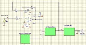
The surprise is that the gain was lower than expected (about 9V/V). I post the simplified schematic below. Could someone point to the correct formula to calculate it?
The simplified schematic is:
Well, I think that things are starting to go really well. I managed to get two high speed probes so I could really adjust the dead time for both mosfets at a time. I have found that the best results are obtained with about 100ns dead time.
With the filter installed (only a two-pole one, 33uH + 1uF capacitor), the idle consumption is about 30mA each rail, so the mosfets hardly heat up a bit.
With load the dissipation increases somewhat, but I have measured about 90% efficiency with a 5Ohms load at about 40W.
Then I connected the feedback resistor to the totem-pole output, and measured gain, bandwidth, etc.
I connected some real audio to the amp, and I must say that it sounds very well. I did a 1hour test at a reasonably high power level and it show reliable, the Mosfets were only warm.
I am about to build the "definitive" version.
The surprise is that the gain was lower than expected (about 9V/V). I post the simplified schematic below. Could someone point to the correct formula to calculate it?
The simplified schematic is:
Attachments
- Status
- This old topic is closed. If you want to reopen this topic, contact a moderator using the "Report Post" button.
- Home
- Amplifiers
- Class D
- My very first Class D pwm (switching) amplifier.