The cct isn't subject to "normal" shoot-through, in fact at zero output both fets are on 50% duty cycle, but are on *at the same time*, not alternately. That would be curtains for a normal totem pole pwm output stage. If I have missed your point please tell me.You need a duty cycle limiter to prevent shoot through on clipping.
This I would like to see. Could you supply a link to save me searching?Motorola has an app note with a discrete design, Linear Technology has a driver IC with it built in.
Meanwhile I'll go out to the shed (it's about 9:25pm Sunday night here and heading toward Winter) and take a few photos like I promised. Should have them posted in 20 minutes or so.
You need a duty cycle limiter to prevent shoot through on clipping.
NO, you definitely don't !!!
Regards
Charles
P.S. The duty cicle limit in the Motorola AN1042 is due to the fact that the output devices are not DC coupled which is a bad idea generally, because you need to limit duty cycle .......
"The cct isn't subject to "normal" shoot-through, in fact at zero output both fets are on 50% duty cycle, but are on *at the same time*, not alternately. That would be curtains for a normal totem pole pwm output stage. If I have missed your point please tell me."
You're right, its been a while since I read the Crown white paper.
For information purposes:
https://www.onsemi.com/pub/Collateral/AN1042-D.PDF
Fig. 6 pp. 13:
http://www.linear-tech.com./pdf/11602fa.pdf
For most switching amplifier topologies shoot through is a problem.
Tripath, for instance, really lowers the switching frequency as the duty cycle approaches 50%.
The LT part actually senses when the off state drain to gate charge has dropped below the gate to source threshold voltage and inhibits the turn on of the other side.
The Crown topology doesn't need this, brain-fade on my part (I already knew the answer but couldn't come up with it in time to keep from sticking foot-in-mouth).
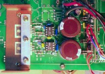
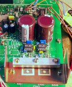
Aww, that's cool djk. ") Anyway, fired it up again tonight with a more robust 40-0-40 volt supply, changed the current sense resistors to 40 mR and organised a better quality audio feed. Power output is now 133 watts into 6 ohms (my test resistor) woohoo! That was 40 volts peak. from about a 41 volt rail. There is still something tricky though. I could only get that power output on a tone burst. If I ran it continuous tone I could get perhaps half that power and then it would go sort of unstable. One clue though is if I touch the metal tab of the schottky that is under the pcb furthest from the edge, the one who's tab is flapping up and down 80 volts, the fuzzy distortion I spoke of the other day gets worse, and if I touch it harder the amp cuts out till I let go. The input wires to the pwm chip are unshielded and only about 2 inches away. Maybe some HF is getting back into there. Have to have a look-see another day.
Anyway, fired it up again tonight with a more robust 40-0-40 volt supply, changed the current sense resistors to 40 mR and organised a better quality audio feed. Power output is now 133 watts into 6 ohms (my test resistor) woohoo! That was 40 volts peak. from about a 41 volt rail. There is still something tricky though. I could only get that power output on a tone burst. If I ran it continuous tone I could get perhaps half that power and then it would go sort of unstable. One clue though is if I touch the metal tab of the schottky that is under the pcb furthest from the edge, the one who's tab is flapping up and down 80 volts, the fuzzy distortion I spoke of the other day gets worse, and if I touch it harder the amp cuts out till I let go. The input wires to the pwm chip are unshielded and only about 2 inches away. Maybe some HF is getting back into there. Have to have a look-see another day.
80v p/p on the load resistor was a sight for sore eyes. Oh yeah.
Anyway, fired it up again tonight with a more robust 40-0-40 volt supply, changed the current sense resistors to 40 mR and organised a better quality audio feed. Power output is now 133 watts into 6 ohms (my test resistor) woohoo! That was 40 volts peak. from about a 41 volt rail. There is still something tricky though. I could only get that power output on a tone burst. If I ran it continuous tone I could get perhaps half that power and then it would go sort of unstable. One clue though is if I touch the metal tab of the schottky that is under the pcb furthest from the edge, the one who's tab is flapping up and down 80 volts, the fuzzy distortion I spoke of the other day gets worse, and if I touch it harder the amp cuts out till I let go. The input wires to the pwm chip are unshielded and only about 2 inches away. Maybe some HF is getting back into there. Have to have a look-see another day.80v p/p on the load resistor was a sight for sore eyes.
Oh yeah.For most switching amplifier topologies shoot through is a problem.
Tripath, for instance, really lowers the switching frequency as the duty cycle approaches 50%.
Shoot through is a problem for most switching amplifiers, that is right - but it is almost indepandant of duty cycle.
Regarding the Tripath amps:
It is vice-versa, i.e. for no input signal the switching frequency is high and it is getting lower with increasing signal level (as usual for sigma-delta modulators).
Regards
Charles
I hit it with a bigger hammer.
Tried a 33k and 1nF LPF at the input to each comparator on the modulator just in case any noise was getting in. That was it! Sounds much much better now. None of that fuzzy crossover-like distortion. Also earthed the centre of the +/- 40v rails - that fixed the problem when I touched one of the schottky's and the amp would cut out. Then I gave it my 6 ohm load and fed the loudspeaker at the same time via a 100 ohm resistor so I could listen to it while it was pumping some real power to "Sultans of Swing".
Anyway, I noticed something interesting. The amp doesn't have any negative feedback which probably helped the situation, but when driven into clipping on music signals you can hardly notice it at all! Often the wave would flatten for as much as 1.5 mS at a time. Peak output at clipping was +/- 39 volts, but for the last 1.5 volts the wave would slow down exponentially and then hit the clip point, or rather it would approach the clip point and then gradually slow down almost asymptotically and gently stop right on the line. When it was time to move away again it would move away at a right angle. No fuss, no bother, no rude noises or oscillations. As a result, on voice signals in particular, the apparent loudness could be wound up quite a bit further than what maximum power would otherwise dictate. Would make a great PA amp I reckon.
When running like this for about 15 minutes the schottky's got to just above skin temperature and the mosfet heatsink to about 35 deg C at about a 15 deg ambient. Judging from the load resistor temp, the average power output would have been about 35-40 watts so I was shoving it reasonably hard. Ahhhhhh....... niceness is radiating out of this amplifier indeed.
Tried a 33k and 1nF LPF at the input to each comparator on the modulator just in case any noise was getting in. That was it!
Sounds much much better now. None of that fuzzy crossover-like distortion. Also earthed the centre of the +/- 40v rails - that fixed the problem when I touched one of the schottky's and the amp would cut out. Then I gave it my 6 ohm load and fed the loudspeaker at the same time via a 100 ohm resistor so I could listen to it while it was pumping some real power to "Sultans of Swing". Anyway, I noticed something interesting. The amp doesn't have any negative feedback which probably helped the situation, but when driven into clipping on music signals you can hardly notice it at all! Often the wave would flatten for as much as 1.5 mS at a time. Peak output at clipping was +/- 39 volts, but for the last 1.5 volts the wave would slow down exponentially and then hit the clip point, or rather it would approach the clip point and then gradually slow down almost asymptotically and gently stop right on the line. When it was time to move away again it would move away at a right angle. No fuss, no bother, no rude noises or oscillations. As a result, on voice signals in particular, the apparent loudness could be wound up quite a bit further than what maximum power would otherwise dictate. Would make a great PA amp I reckon.
When running like this for about 15 minutes the schottky's got to just above skin temperature and the mosfet heatsink to about 35 deg C at about a 15 deg ambient. Judging from the load resistor temp, the average power output would have been about 35-40 watts so I was shoving it reasonably hard. Ahhhhhh....... niceness is radiating out of this amplifier indeed.
Veeery interesting
Hello, Ciclotron.
It seems that you have finally put your amplifier to work! Good news!
I am also starting to feel like building a Class D amplifier basing on Crown's BCA technology, but have some doubts:
How do you calculate the ouput filter?
What are the required ratings of the schottky diodes?
By the way, you have used a crap SMPS from a car amplifier or so, aren't you? Or is it a Class D amplifier? (just for curiosity)
Best regards from Spain.
Re: Veeery interesting

Schottky diodes should have a voltage rating of whatever the total dc voltage rails are. I will eventually have + / - 50vdc so I have used 100v diodes. Schottky diodes are MUCH better than normal fast recovery diodes here - you don't have to worry about reverse recovery current and all the noise that goes with it.
Not sure what you mean 'have I used a crap car amplifier, or Class D amplifier? If you mean what was the pcb originally, it was for generating 75VAC 30VA 25Hz sinewave for ringing telephone bells.
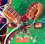
I didn't really calculate the output filter, I just used something from my junk box that looked about right.ssanmor said:How do you calculate the ouput filter?
What are the required ratings of the schottky diodes?
By the way, you have used a crap SMPS from a car amplifier or so, aren't you? Or is it a Class D amplifier? (just for curiosity)
Schottky diodes should have a voltage rating of whatever the total dc voltage rails are. I will eventually have + / - 50vdc so I have used 100v diodes. Schottky diodes are MUCH better than normal fast recovery diodes here - you don't have to worry about reverse recovery current and all the noise that goes with it.
Not sure what you mean 'have I used a crap car amplifier, or Class D amplifier? If you mean what was the pcb originally, it was for generating 75VAC 30VA 25Hz sinewave for ringing telephone bells.
Wow! Thanks anelar.anelar said:Always fun to read about your projects! Nice work...

I am going to post the schematic one day soon.
Thanks, Ciclotron.
And another question...
What kind of MOSFETs do you use? P and N or only N-channel?
If they are N-channel, I would be very interested in knowing how you drive them. It seems that you don't use transformers nor optocouplers. Could you provide more details on that?
Thanks for your soon response!
And another question...
What kind of MOSFETs do you use? P and N or only N-channel?
If they are N-channel, I would be very interested in knowing how you drive them. It seems that you don't use transformers nor optocouplers. Could you provide more details on that?
Thanks for your soon response!
that limits your audio passband to about 4.8 KHz, doesn't it?
I have a distinctive suspicion that he will use it to substitute his subwoofer amp that went up in smoke
Regards
Charles
- Status
- This old topic is closed. If you want to reopen this topic, contact a moderator using the "Report Post" button.
- Home
- Amplifiers
- Class D
- My very first Class D pwm (switching) amplifier.