I have decided to try and make a homemade D-Class amp useing the new TAS5630 chip from Texas Instruments.
The specs on it are amazing like total output power 600W, low THD (0,03%) single supply 20-50V operation, differential analog inputs.... and on top of it all its almost as simple to use as a AB class chip amp.
So all this made me decide to try and build one of them.
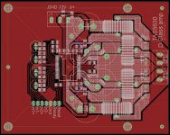
Right now i have a PCB made in eagle for the HSSOP version of the chip( The TQFP version i wanted is not in production yet) and i just recently got the chips them selfs .As you can see i am using the BTL mode of it that has a max of 300W but the high power is mealy to provide headroom and keep the amp cold.
On the PCB the 4 holes you see are not for the purpose of mounting the PCB but they are 775 CPU socket push pin heatsink mountings. I just toght why not simply use a CPU heatsink to cool this. As for the white you see around the board thats the solder mask stop layer so i can cover those in solder to provide a better connection in the high current paths.
The specs on it are amazing like total output power 600W, low THD (0,03%) single supply 20-50V operation, differential analog inputs.... and on top of it all its almost as simple to use as a AB class chip amp.
So all this made me decide to try and build one of them.
Right now i have a PCB made in eagle for the HSSOP version of the chip( The TQFP version i wanted is not in production yet) and i just recently got the chips them selfs .As you can see i am using the BTL mode of it that has a max of 300W but the high power is mealy to provide headroom and keep the amp cold.
On the PCB the 4 holes you see are not for the purpose of mounting the PCB but they are 775 CPU socket push pin heatsink mountings. I just toght why not simply use a CPU heatsink to cool this. As for the white you see around the board thats the solder mask stop layer so i can cover those in solder to provide a better connection in the high current paths.
Attachments
Like your PC heatsink idea... Just need to make sure all the
topside stuff is shorter than the thermal interface top of the
chip... Means flush cutting some rather large thruhole parts
too, from the look of it. Sometimes that makes for mechanical
weakness... You might want to build up big fillets the other
side. Agh, but you just said single layer???
I am looking forward to seeing this as an EVM. Or maybe
already did, but it looked different in some way??? All I can
remember: Some early boards were built without a device.
I never got to see the heatsink that would have gone with.
Would have wanted to play with that one for sure!
I got to burn the purepath CDs that shipped with the 3108,
I'm not sure Purepath for 3208 was/is exactly the same CD
or not??? You best get that update from an official source.
I don't wanna endrun around my bread and butter.
I'll mention it to the relevant engineer next time I see him.
But I'm down the street, and that might not happen quick.
Thats good to hear i would also like to hear about your progress. For my board i looked at the PCB in the datasheet for the TQFP version and made something close to that.
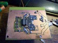
Right now i have to etch this board, i hope it comes out alright despite the printer problems. With luck it should be assembled tomorrow. I hope it will actually work.
Right now i have to etch this board, i hope it comes out alright despite the printer problems. With luck it should be assembled tomorrow. I hope it will actually work.
I pull up my build (last CD we shipped for 3108), and your
chip (3208) does seem to be listed prominently in the GDE.
I'm not sure thats relevant to what CD ships with a 3208?
That software isn't mine to give out. Again, I don't work
directly inside TI, nor have any such authority. The other
guy who actually does work at TI might be able to point
the way to more direct help?
I just do whatever TI contracts us to do, I'm not part of
the decision making process.. I'm just bench tech at the
end of a line that sometimes gets to assemble the EVMs.
Best I can do is mention it to the engineer if I happen to
see him. But that could be a while. Not here very often.
I'll ask my supervisor for permission to call him directly.
If you can make a nice switch mode for it it would be a great car amp since it only needs a single supply 20-50V to work.
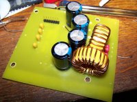
Oh and i looked trough your page and you made some nice amp and switchmode projects. It gave me a toght to build a switchmode my self. Right now i use a huge, heavy as hell toroid.
Oh and i looked trough your page and you made some nice amp and switchmode projects. It gave me a toght to build a switchmode my self. Right now i use a huge, heavy as hell toroid.
Yea go for it, they are pretty simple, I had one for my first car amp, powering LM3886 @ +/-30v, that was cool and all, then I wanted something from Tripath [there were other amps, all AB], since this is PWM amp, so I got myself AMP2 from 41hz.com and made a bit too huge supply for it, so now I'm looking into getting AMP7 also 
But this little IC, if it does what they say, it could be something use for highs in car [for normal users, whole set of front speakers]
Will see how this will turn out, so far I like it very much
As for you, yea try 12v smps, something small, say one from Risto80 on this forum, that was my first smps, working great and simple to study what is going on, what is important and what not so much
Oh misunderstood the shutdown pin its a output to indicate device is not in a error state and it is 0 meaning the device is shut down and dose not react to the reset signal.After some diging in the datasheet i found that the SD pin remains low no mater what when the device is preforming the so called PPSC (Pin to Pin Short Circuit protecion) and is Dependant on the output inductor... hmm the inductance of a open cirucit is something like infinite uH that means i have to wait infinite seconds for the amp to complete the procedure.... i dont think i have that much time.
Anyway this means i have to build the 2nd channel too.... damn where to find those bootstrap caps.
Anyway this means i have to build the 2nd channel too.... damn where to find those bootstrap caps.
- Status
- This old topic is closed. If you want to reopen this topic, contact a moderator using the "Report Post" button.
- Home
- Amplifiers
- Class D
- TAS5630 D-Class build